Metrohm 753 Suppressor Module User Manual
Page 37
4 Malfunctions – Maintenance
753 Suppressor Module / 8.753.1003 Instructions for Use
34
•
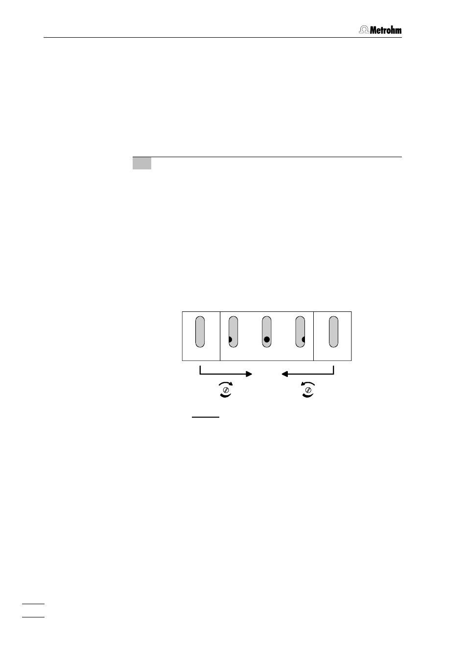
By rotating the suppressor block or with the aid of a mirror
check the position of the suppressor rotor according to Fig.
10: at least one of the three holes of the suppressor rotor
must be partly or completely visible through the opening at
the bottom of the suppressor block.
•
Repeat the procedure 2-3 times; wait at least 10 s each time
before the
•
If the rotor stops in an unacceptable position then the braking
range must be readjusted (continue with point 3).
3 Adjust braking range
•
Rotate adjustment screw 18
18 a little in each direction accord-
ing to Fig. 10 so that the rotor position lies in the acceptable
range.
•
Operate key 88
•
Check the position of the rotor in all of the 3 possible posi-
tions according to Fig. 10.
•
Repeat the adjustment procedure until the position of the
rotor lies in the acceptable range in all of the 3 possible posi-
tions. Wait at least 10 s each time before operating key 88
optimal
zulässig
zulässig
unzulässig
unzulässig
Fig. 10: Adjusting the braking range
not acceptable
not acceptable
acceptable
acceptable
optimum