Metrohm 753 Suppressor Module User Manual
Page 14
2.3 Connection to the 690 Ion Chromatograph
753 Suppressor Module / 8.753.1003 Instructions for Use
11
2 Connect suppressor block
•
Remove the plastic stopper from opening 17
17 on the rear wall
of the 690 Ion Chromatograph and push cable 23
23 mounted
on the suppressor block 21
21 through this opening.
•
Connect cable 23
23 to connection 17
17 “Suppressor“ of the 753
Suppressor Module (see Fig. 5).
3 Connect column to injector
•
Connect separating column 63
63 to capillary connection 65
65
leading to the injector according to section 3.7 of the 690 In-
structions for Use.
4 Rinse column
•
Rinse separating column 63
63 with eluent for about 10 min
according to section 3.7 of the 690 Instructions for Use.
5 Connect column to suppressor
•
Screw inlet capillary 24
24 marked with "Eluent" at suppressor
connection 22
22 (see Fig. 6) to outlet end of separating column
63
63 using a 6.2744.010 compression fitting.
6 Connect suppressor to detector block
•
Screw outlet capillary 29
29 marked with "Detector" at suppres-
sor connection 22
22 to a 6.2620.060 coupling using a
6.2744.010 compression fitting.
•
Screw inlet capillary 59
59 of detector block 54
54 to the other end
of the 6.2620.060 coupling.
1
3
2
24
24
27
27
28
28
29
29
25
25
26
26
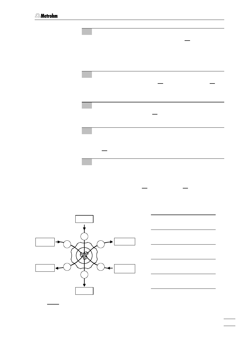
Fig. 6:
Connections at suppressor
24
24
Suppressor inlet
capillary for eluent
25
25
Suppressor inlet
capillary for H
2
SO
4
26
26
Suppressor outlet
capillary for H
2
SO
4
27
27
Suppressor outlet
capillary for H
2
O
28
28
Suppressor inlet
capillary for H
2
O
29
29
Suppressor outlet
capillary for eluent
H
2
O
H
2
SO
4
Waste
Eluent
Detector
Waste