Metrohm 753 Suppressor Module User Manual
Page 34
4.2 Maintenance and servicing
753 Suppressor Module / 8.753.1003 Instructions for Use
31
38
38
37
37
36
36
35
35
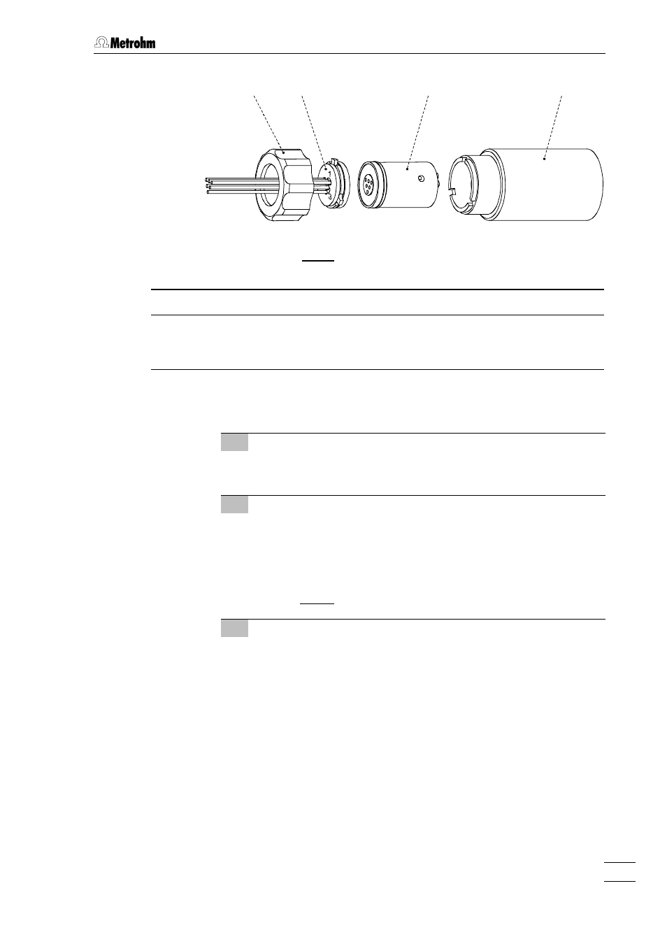
Fig. 9: Assembling the suppressor
35
35
Screw nut
37
37
Suppressor rotor (6.2832.000)
36
36
Connection piece
(6.2832.010)
with input and output leads
38
38
Suppressor holder
6 Clean connection piece
•
Clean the sealing surface of connection piece 36
36 with the aid
of a lint-free cloth and ethanol.
7 Insert connection piece
•
Insert connection piece 36
36 in suppressor holder 38
38 in such a
way that connection "1" is at the top and that the three lugs on
the connection piece fit in the corresponding openings of the
holder.
•
Screw nut 35
35 onto the thread of suppressor holder 38
38 manu-
ally (do not use tools).
8 Connect and condition the suppressor
•
Reconnect the suppressor to the IC system (see section 2.3.2
and section 2.4.2).
•
Before switching the suppressor to the next position for the
first time rinse all 3 suppressor units with solution for 5 min.
- 915 KF Ti-Touch (382 pages)
- 800 Dosino (53 pages)
- 767 Calibrated Reference (23 pages)
- 940 Professional IC Vario ONE/SeS/Prep 2 (54 pages)
- 754 Dialysis Unit (49 pages)
- 815 Robotic Soliprep for LC (76 pages)
- Vision Manual (207 pages)
- tiamo 2.1 Manual (1532 pages)
- 825 Lab Link (37 pages)
- 808 Titrando (70 pages)
- 902 Titrando (52 pages)
- 756 KF Coulometer (163 pages)
- 756 KF Coulometer (162 pages)
- 940 Professional IC Vario ONE/LPG (98 pages)
- 850 Professional IC Anion MCS Prep 3 (154 pages)
- 850 Professional IC Anion MCS Prep 3 (152 pages)
- 904 Titrando (58 pages)
- 850 Professional IC Anion MSM-HC MCS Prep 2 (150 pages)
- 930 Compact IC Flex Oven/ChS/Deg (47 pages)
- 872 Extension Module Liquid handling (64 pages)
- 814 USB Sample Processor (90 pages)
- 814 USB Sample Processor (91 pages)
- 940 Professional IC Vario (43 pages)
- Vision – Tutorial (40 pages)
- 799 GPT Titrino (242 pages)
- 889 IC Sample Center (68 pages)
- 761 Compact IC (228 pages)
- 851 Titrando (100 pages)
- 748 DH Sample Changer (32 pages)
- 940 Professional IC Vario ONE/SeS/HPG (51 pages)
- 896 Professional Detector – Amperometry (62 pages)
- 877 Titrino plus (139 pages)
- 881 Compact IC pro – Anion (129 pages)
- 940 Professional IC Vario ONE/ChS/HPG (112 pages)
- 930 Compact IC Flex Deg (41 pages)
- 840 PC Control 5.0 / Touch Control (351 pages)
- 940 Professional IC Vario ONE/Prep 1 (45 pages)
- 776 Dosimat (42 pages)
- 717 Sample Changer (36 pages)
- 815 Robotic USB Sample Processor XL (113 pages)
- 815 Robotic USB Sample Processor XL (114 pages)
- 940 Professional IC Vario ONE/SeS/PP (126 pages)
- 838 Advanced Sample Processor Installation Instructions (109 pages)
- 700 Dosino (55 pages)
- 719 S Titrino (152 pages)