Metrohm 753 Suppressor Module User Manual
Page 12
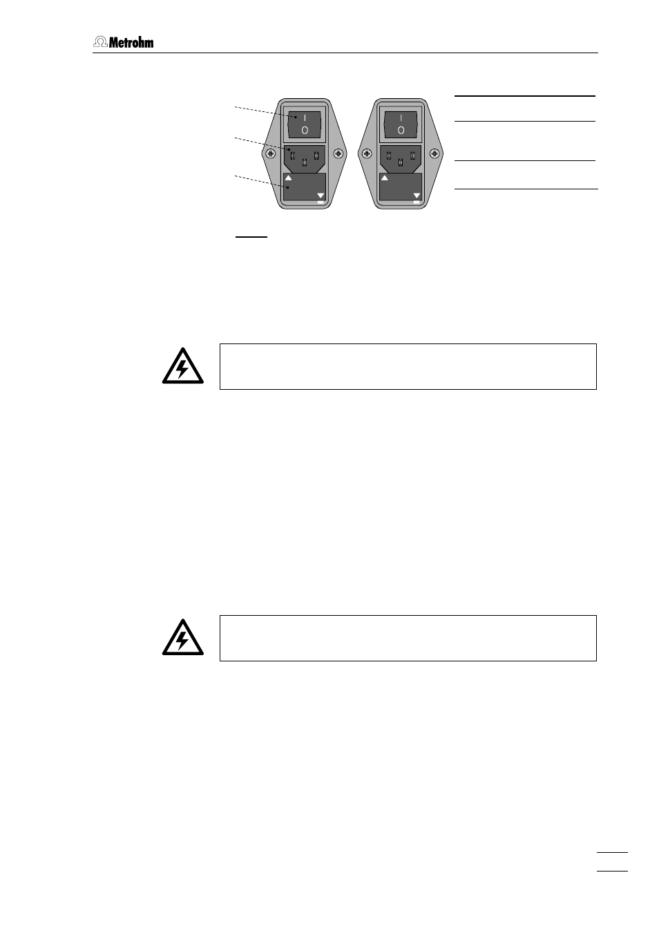
2.2 Mains connection
753 Suppressor Module / 8.753.1003 Instructions for Use
9
13
13
220 -- 240 V
100 -- 120 V
19
19
20
20
220 -- 240 V
100 -- 120 V
Fig. 4: Setting the mains voltage
2.2.2
Fuses
One of the two fuses 0.5 A/slow-blow for 100
…
120 V or 0.25 A/slow-
blow for 220
…
240 V is installed in fuse holder 20
20 of the 753 Suppressor
Module as standard.
Ensure that the instrument is never put into operation with fuses of
another type, otherwise there is danger of fire!
For checking or changing fuses, proceed as described in section 2.2.1.
2.2.3
Mains cable and mains connection
Mains cable
The instrument is supplied with one of three mains cables:
•
6.2122.020 with plug SEV 12 (Switzerland,
…
)
•
6.2122.040 with plug CEE(7), VII (Germany,
…
)
•
6.2133.070 with plug NEMA 5-15 (USA,
…
)
which are three-cored and fitted with a plug with an earthing pin. If a
different plug has to be fitted, the yellow/green lead (IEC standard)
must be connected to protective earth (protection class I).
Any break in the earthing inside or outside the instrument can make it
a hazard!
Mains connection
Plug the mains cable into mains connection plug 19
19 of the 753 Sup-
pressor Module (see Fig. 4).
2.2.4
Switching the instrument on/off
The 753 Suppressor Module is switched on and off using mains switch
13
13. When the instrument is switched on lamp 11 lights up.
100 – 120 V
220 – 240 V
13
13 Mains switch
19
19 Mains connec-
tion plug
20
20 Fuse holder