Camera led indicator, 4 attaching the propellers, 1 introduction – DJI Phantom 2 Vision Plus User Manual User Manual
Page 15: 2 assembly, Propeller (p15), Camera led indicator (p15)
Assembly and Use
©
2014 DJI. All Rights Reserved.
15
Camera LED Indicator
Camera LED Indicator lights up after the flight battery is powered on. It provides information on the working status of the
camera.
Camera LED Indicator
Wi-Fi status
Camera status
Green Solid
OFF
Power On; Idle
Slow Green Blink (0.2s on, 1.8s off)
ON
Idle
Green Blink(0.1s on, 0.3s off, 0.1s on, 1.8s off) ON
Micro-SD card connected to PC
Fast Green Blink (0.1s on, 0.3s off)
ON
Synchronizing
Orange Solid
OFF
Recording
Orange Blink Once (0.2s on, 0.3s off)
ON / OFF
Taking a single picture.
Orange Blink 3 Times(0.1s on, 0.1s off)
ON / OFF
Taking 3 or 5 photos per shot
Orange Fast Blink (0.1s on, 0.3s off)
ON / OFF
Firmware Upgrading
Green, Orange (0.2s green, 1.8s orange) ON
Recording
Red Solid
ON / OFF
Critical error
Slow Red Blink (0.2s on, 1.8s off)
ON / OFF
CMOS sensor error
Red Blink Once (0.2s on, 0.3s off)
ON / OFF
Operation failed
Red Blink 3 Times(0.1s on, 0.1s off)
ON / OFF
Micro-SD card error
Fast Red Blinks (0.1s on, 0.3s off)
ON / OFF
Upgrade error
Fast Green, Orange and Red Blink
(0.1s on, 0.3s off)
ON / OFF
Overheated Camera
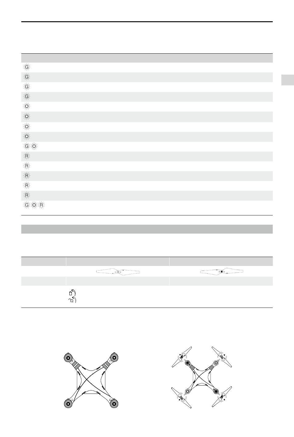
4 Attaching the Propellers
Always use original 9-inch propellers, classified by the color of each central nut.
4.1 Introduction
Propellers
Grey Nut (9450)
Black Nut (9450 R)
Diagram
Assembly Location Attach to motor without black dot.
Attach to motor with black dot.
Fastening/
Un-fastening
Instructions
Lock: Tighten propeller in this direction.
Unlock: Loosen propeller in this direction.
4.2 Assembly
(1) (Figure 20) Remove warning cards from motors after you have read them.
(2) (Figure 21) Spin grey marked propellers clockwise onto unmarked motors and black marked propellers anti-
clockwise for black marked motors.
Figure 20
Figure 21
Attaching the Propellers