Brandmotion 1022-9590 User Manual
Page 10
!"#$%&&%$!'"(!"#$)*+$!'"#
9581 Instructions 4-18-13.doc
10 of 13
Step 54. Starting at the bottom, cut the tape covering
the wiring until you can pull it back all the way to the
top.
Step 55. Using Delphi Terminal Tool 12094429 or
a
Small Watch Repair Screwdriver
, release the white terminal
lock on the 16-pin connector. The tab will only lift about
1/10
th
of an inch.
(Figures 14 & 15).
Figure 14
Figure 15
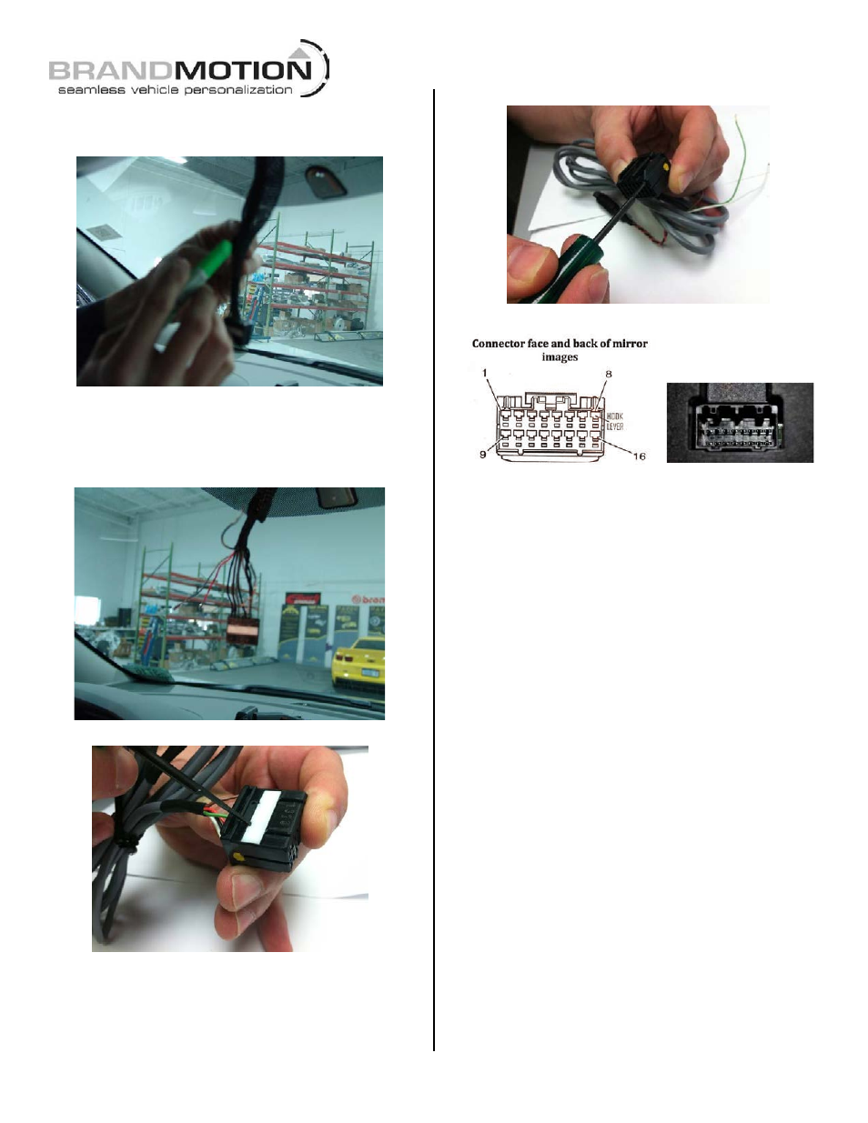
Step 56. Using Delphi Terminal Tool 12094429
or a
Push Pin, remove the wires from pins 6, 7, 8, 9 and 13.
Insert the tool into the face of the connector to lift the
plastic tab that holds the pin in place then press the pin
out (refer to Figures 16 & 17).
Figure 16
Figure 17
NOTE: It may not be necessary to use the loose Green,
White, & Brown wires on the supplied Mirror Harness as
most GM vehicles already have these locations populated. If
wires already exist in these locations, test the leads using a
Multimeter for the correct signal.
Step 57. If wires exist in cavities 6 or 7 of the 16-pin
connector, remove and isolate them with tape. If wire
exists in cavities 8, 9, or 13 (and are active by checking
with a Multimeter) isolate the loose Black, Green or Red
wires on the Mirror Harness and cover with Electrical
Tape.
Step 58. IMPORTANT: If the vehicle you are working
has a wire in the Low Speed LAN Circuit cavity 3, you
MUST remove and isolate it from the mirror connector by
covering it with Electrical Tape. Not doing so will cause
the vehicle computer to malfunction and the vehicle will
not start.
Step 59. Using the kit supplied Mirror Harness, plug
white wire into pin 6 of the 16-pin connector until it
clicks into place. Repeat by plugging the brown wire into
pin 7, the black wire into pin 8, the green wire into pin
9, and the red wire into pin 13.
Step 60. Press down on the white lock tab of the 16-pin
connector to secure the wires.