Bpm-e data connections – Bird Technologies 3129 Display User Manual
Page 33
17
BPM-E Data Connections
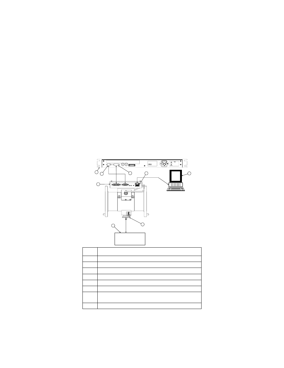
The BPM-E has an RS-232 connector and an ethernet connector. The RS-232 con-
nector conducts ASCII data between the BPM-E and a display panel or a PC. The
ethernet connector conducts data between the BPM-E and a network device (hub,
router, PC with network capability). Figure 8 on page 17 shows how a BPM-E can
be connected to a Bird 3129 Digital Display. RS-232 pin numbers and descriptions
are given in Figure 10 on page 18. When you connect using the RS-233 port, you
will use the PCTool software utility to communicate with the BPM-E.
If you connect the BPM-E to the rear panel of a 3129 Digital Display (RS-232 con-
nection), you can also connect a PC to the RS-232 connector on the front of the
display (Remote connector) to communicate with the BPM-E.
The ethernet connector provides a means for you to connect the BPM-E to a
network or directly to a computer with ethernet capability that is not connected
to a network. When you use the ethernet capability, you will also use the WebT-
ool utility to set the IP address, configure the BPM-E, and monitor the power
and alarm status of the transmission line.
Figure 8 BPM-E Rear Panel Data Connections
Item
Description
1
3129 Digital Display, rear panel
2
RS-232 communication port, 9-pin
3
Power/Alarm connector, 15-pin
4
Ethernet connector (for network or local PC)
5
Computer (for network or local PC)
6
Sampler port
7
Monitor device (network analyzer, modulation monitor,
oscilloscope)
8
BPM-E controller
NETWORK ANALYZER
MODULATION MONITOR
OSCILLOSCOPE
1
2
3
4
5
6
7
8
Cleveland, Ohio USA
Phone: (440) 248-1200
www.bird-electronic.com
MODEL 3129
S/N
Electronic Corporation
FUSE 1.0A, 250 V
115/230 VAC
50/60 Hz
.6A MAX.
LINE
CL
OS
ED
NO
AL
RM
OP
EN
NO
AL
RM
CO
MM
ON
FO
R A
LR
M
AL
RM
TT
L O
UT
RE
MO
TE
RE
SE
T
GR
OU
ND
RFL
ANALOG OUTPUT
FWD
POWER/ALARM
SENSOR INTERFACE
RS-232