Component description – Bird Technologies 3129 Display User Manual
Page 19
3
Component Description
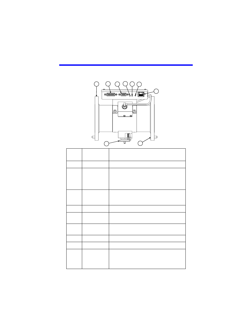
Figure 1 BPM-E Components
Item
Function
Description
1
RF Input
Input to BPM-E from transmitter
2
Power/Alarm
Parallel Port
Connects to the 3129 digital display using a
15 pin cable.
Note:
Also used for remote
operation.
3
RS-232 Serial
Port
Connects to a 3129 digital display, a PC, or
other display panel using a 9 pin RS-232
cable
4
Alarm LED
Red LED, lights when an alarm is triggered
5
Monitor On
LED
Green LED, lights when the unit is powered
6
Reset Switch
Press to reset the alarm. If an alarm trigger
is still present, the alarm will reactivate
7
Ethernet Port
Connects to a network or PC ethernet card
8
RF Output
Output from BPM-E to antenna or load
9
RF Test Port
Insert a sampling element with an
appropriate connector to connect to a
monitor device (e.g. spectrum analyzer,
modulation monitor, oscilloscope)
1
2
3
4
5
6
7
8
9