Flanged connector unflanged connector – Bird Technologies 3129 Display User Manual
Page 29
13
Flanged Connector
To connect a flanged unit to a flanged RF transmission line, use an appropriate
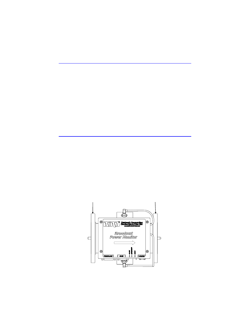
coupling kit. Refer to Figure 5, page 13 for RF input and output orientation.
1.
Insert the center connector (bullet).
Note:
Push the connector until it is fully seated.
2.
Connect the coaxial input in a straight line.
Note:
Push carefully to close.
3.
Insert the bolt sets.
4.
Tighten the bolt sets evenly all around to transmission line manufacturer’s
recommended torque.
Note:
Use all of the bolts.
Unflanged Connector
To connect an unflanged unit to an unflanged RF line, use an appropriate cou-
pling kit.
1.
Insert the center connector (bullet).
Note:
1.Push the connector until it is fully seated.
2.
Position the outer sleeve, with clamping bands, over the input connector.
3.
Set the transmission line snugly against the coupling stops.
4.
Position the clamping bands evenly about 3/4” from the ends of the sleeve.
5.
Tighten the clamping bands.
Figure 5 BPM-E Flanged Line Sections, RF Direction
RF INPUT
RF OUTPUT