Mounting a 3129 digital display, Ac power connector, Alarm interlocks – Bird Technologies 3129 Display User Manual
Page 30: 3129 digital display
14
3129 Digital Display
Note:
When using with a BPME, it is recommended to connect the
3129 directly to a universal power source (UPS).
Mounting a 3129 Digital Display
Install the digital display in a standard (1U) rack mount.
AC Power Connector
The AC Power connector (Figure 2 on page 4) provides operating power for the
digital display and the BPM-E electronics. The AC power supply cord is also the
line disconnect device for this product. You can use any approved power cord to
connect to the digital display, such as domestic type SVT, 300 VAC, 18 AWG, 10
A, 3 conductor (including ground) or international type H05VV-F, 300 VAC, 1.00
mm, 10 A, 3 conductor (including ground).
Alarm Interlocks
When an alarm occurs, the 3129 Digital Display utilizes one of the follwing two
methods to shut down your system.
•
A TTL signal (Alarm TTL Out) that goes low on alarm
•
A relay (alarm relay) that de-energizes on alarm
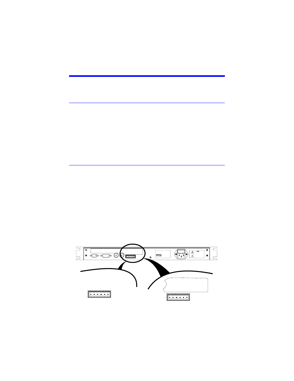
The alarm interlocks are available at the alarm interlock connector at the rear of
the unit (Figure 6, page 14).
Note:
The alarm relay label text has been revised for clarity. If you
are connecting to an older Bird 3129 display, the alarm interlock con-
nector might have the “old label” text.
Figure 6 Alarm Interlock Connections
1
Cleveland, Ohio USA
Phone: (440) 248-1200
www.bird-electronic.com
MODEL 3129
S/N
Electronic Corporation
FUSE 1.0A, 250 V
115/230 VAC
50/60 Hz
.6A MAX.
LINE
CL
OS
ED
NO
AL
RM
OP
EN
NO
AL
RM
CO
MM
ON
FO
R A
LR
M
AL
RM
TT
L O
UT
RE
MO
TE
RE
SE
T
GR
OU
ND
RFL
ANALOG OUTPUT
FWD
POWER/ALARM
SENSOR INTERFACE
RS-232
OLD LABEL
NEW LABEL
AL
RM
NO
RM
CL
SD
AL
RM
NO
RM
OP
EN
AL
RM
CO
MM
ON
AL
RM
TT
L O
UT
RE
MO
TE
RE
SE
T
GR
OU
ND
CL
OS
ED
NO
AL
RM
OP
EN
NO
AL
RM
CO
MM
ON
FO
R A
LR
M
AL
RM
TT
L O
UT
RE
MO
TE
RE
SE
T
GR
OU
ND
1 2 3 4 5 6