S 12, Bpm-e7 – Bird Technologies 3129 Display User Manual
Page 28
12
BPM-E7
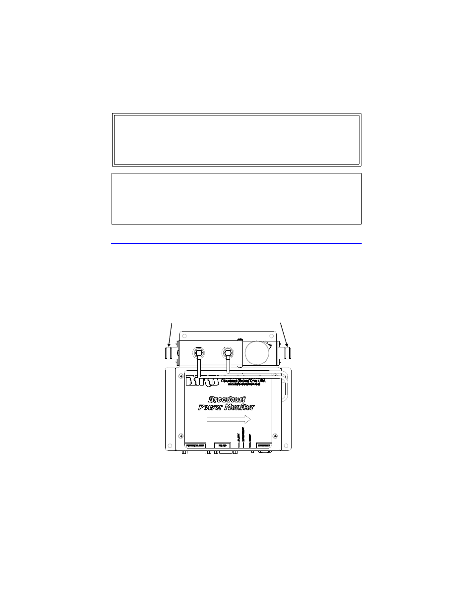
The BPM-E uses QC-type quick change connectors. Use 50 ohm coaxial cable
such as RG-218/U or RG-220/U (-17A or -19A), appropriate for the frequency and
power level of operation. Use a cable connector that will mate with both the
transmission line and the BPM-E7. Connect the BPM-E7 to the RF line as shown
in Figure 4, page 12.
Figure 4 BPM-E 7, RF Direction
WARNING
High RF voltage and energy is always present in the RF Test Port when the
system is operating. Do not operate the system if the BPM-E RF Test Port is
open. Close the port with a dummy plug or a suitable sampling plug. Failure
to comply may result in severe burns, electrical shock, or death.
CAUTION
BPM-E signal sensing couplers are fixed in place. Do not attempt to remove or
rotate the couplers. They are calibrated and oriented at the factory and are not
designed to be rotated or removed by the end user. Failure to comply may result
in loss of calibration and accuracy, and in permanent damage to the unit.
RF INPUT
RF OUTPUT