Alarm parameters – Rockwell Automation 1606-XLP XM Electronic Overspeed Detection System User Manual
Page 52
Publication GMSI10-UM015B-EN-E - June 2011
52 Configuring the XM EODS
Alarm Parameters
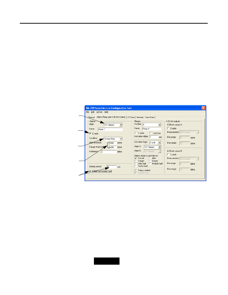
Use the Alarm, Relay and 4-20 mA Output tab in the XM-220 Speed Module
Configuration Tool to select the type of measurement that is associated with
an alarm and to set the alert and danger threshold values.
The XM-220 provides a total of eight alarms, four per channel. Each alarm is
permanently associated with a particular measurement.
To configure the alarm parameters, follow these steps:
1. In the XM-220 Speed Module Configuration Tool, click the Alarm,
Relay, and 4-20 mA tab. You will see a screen similar to this.
2. Select the Alarm that you want to configure.
3. Enter or select the desired parameters to set up the behavior of the
alarm. This includes:
• the measurement and channel associated with the alarm
• the measurement values at which the alarm changes state
• the amount that the measurement must fall before the alarm
condition is cleared (hysteresis)
• whether to prohibit the tachometer fault during the startup period
• the length of time that the tachometer fault is inhibited after the
startup signal is received
This checkbox must be checked
in order to use the alarm.
The measurement and channel
associated with the alarm.
Determines on which side of the
threshold values the alert and
danger conditions exist.
The threshold values for the alert
and danger threshold conditions.
Enter the length of time that the
tachometer fault is disabled if
Inhibit tachometer fault
checkbox is checked.
TIP
Refer to Chapter 3 in the XM-220 Dual Speed
Module User Guide for a detailed description of the
configuration parameters.