Rockwell Automation 1606-XLP XM Electronic Overspeed Detection System User Manual
Page 23
Publication GMSI10-UM015B-EN-E - June 2011
Installing the XM Electronic Overspeed Detection System 23
Use the following steps to install the terminal base on a wall or panel. We
recommend you mount the XM-946 terminal base first, next to the power
supply modules (see Figure 2.7 on page 29).
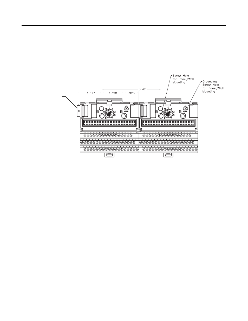
1. Lay out the required points on the wall/panel as shown in the drilling
dimension drawing below.
2. Drill the necessary holes for the #6 self-tapping mounting screws.
3. Secure the XM-946 terminal base unit using two #6 self-tapping screws.
4. To install the XM-941 terminal base unit, retract the side connector into
the base unit. Make sure it is fully retracted.
5. Position the terminal base unit up tight against the neighboring terminal
base. Make sure the hook on the terminal base slides under the edge of
the terminal base unit.
6. Gently push the side connector into the side of the neighboring terminal
base to complete the backplane connection.
7. Secure the terminal base to the wall with two #6 self-tapping screws.
8. Repeat steps 4-7 to install the other two XM-941 terminal base units.
Side Connector