Connecting the transducers, Connecting a proximity probe transducer, Important – Rockwell Automation 1606-XLP XM Electronic Overspeed Detection System User Manual
Page 37
Publication GMSI10-UM015B-EN-E - June 2011
Installing the XM Electronic Overspeed Detection System 37
Connecting the Transducers
The XM-220 modules can accept input signals from either a proximity probe
transducer or magnetic pickup. The three individual transducers are connected
to Channel 1 (terminals 0 and 16) of each of the XM-220 modules. For wiring
connections pertaining to Channel 2, refer to the XM-220 Dual Speed Module
User Guide.
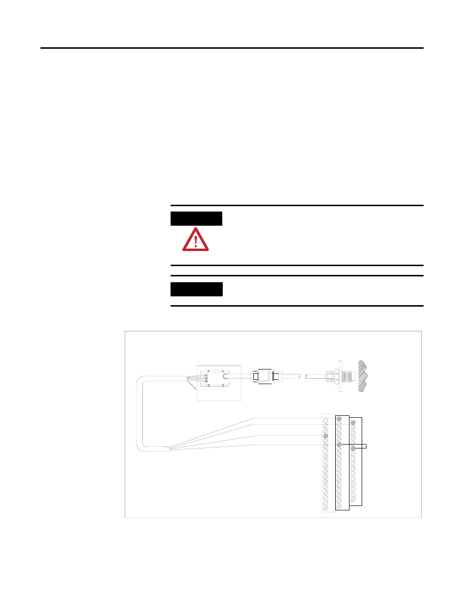
Connecting a Proximity Probe Transducer
The figure below shows the wiring of a proximity probe transducer to Channel
1 of the XM-220 module.
Figure 2.16 Proximity Probe Sensor to Channel 1 Wiring
ATTENTION
You may ground the cable shield at either end of the cable.
Do not ground the shield at both ends. Recommended
practice is to ground the cable shield at the terminal base
and not at the transducer. Any convenient Chassis terminal
may be used (see Terminal Block Assignments on page 27).
IMPORTANT
The internal transducer power supply is providing power to
the non-contact sensor.
COM
SIG
-24
Channel 1 Input Signal
-24V DC
0
16
Signal Common
21
5
Jumpering terminal
5 to terminal 21
configures CH 1 buffer
for -24V to 9V
Isolated Sensor Driver
Shield
Shield
Floating
37
TYPICAL WIRING FOR NON-CONTACT SENSOR
TO XM-220 DUAL SPEED MODULE CHANNEL 1