Typical xm eods wiring diagram, Connecting the power supply modules, Figure 2.7 typical xm eods wiring connections – Rockwell Automation 1606-XLP XM Electronic Overspeed Detection System User Manual
Page 29
Publication GMSI10-UM015B-EN-E - June 2011
Installing the XM Electronic Overspeed Detection System 29
Typical XM EODS Wiring Diagram
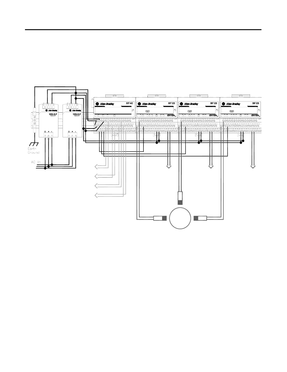
Figure 2.7 shows the typical XM Electronic Overspeed Device System wiring
configuration. See the following topics for specific wiring information.
Figure 2.7 Typical XM EODS Wiring Connections
Connecting the Power Supply Modules
The power supply to the XM-442 module is 24V dc. The XM-442 provides
two 24V dc power supply connections. The connections are electrically
isolated from each other so a power interruption to one connection does not
affect the other connection. This allows you to have a redundant power supply
for the XM EODS. The XM-442 also provides terminals (16 and 34) for
monitoring the primary and secondary EODS power supply modules.
VOTED EODS RELAY
1440-REX03-04RG
DUAL SPEED
1440-SPD02-01RB
DUAL SPEED
1440-SPD02-01RB
DUAL SPEED
1440-SPD02-01RB
EODS Events
(3)
Transducer
Transducer
Shutdown
Relay #1
Shutdown
Relay #2
Shutdown
Relay #3
Alarm
Relay
Circuit
Fault
Relay
Circuit
Fault
Relay
Circuit
Fault
Relay
Transducer