Connecting a magnetic pickup sensor – Rockwell Automation 1606-XLP XM Electronic Overspeed Detection System User Manual
Page 38
Publication GMSI10-UM015B-EN-E - June 2011
38 Installing the XM Electronic Overspeed Detection System
Connecting a Magnetic Pickup Sensor
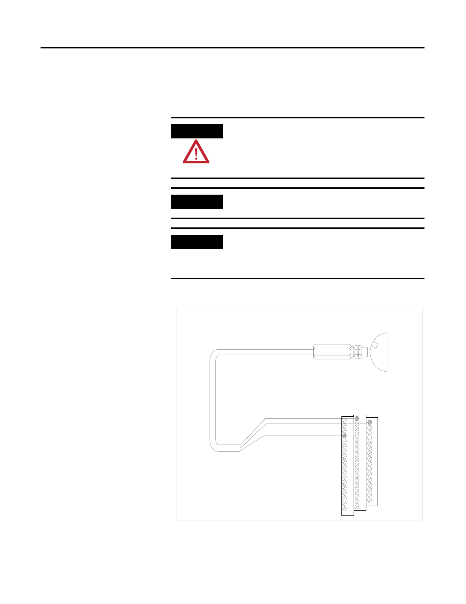
The figure below shows the wiring of a passive magnetic pickup sensor to
Channel 1 of the XM-220 module.
Figure 2.17 Magnetic Pickup to Channel 1 Wiring
ATTENTION
You may ground the cable shield at either end of the cable.
Do not ground the shield at both ends. Recommended
practice is to ground the cable shield at the terminal base
and not at the transducer. Any convenient Chassis terminal
may be used (see Terminal Block Assignments on page 27).
IMPORTANT
The module does not power the sensor. It measures only
the input voltage.
IMPORTANT
An internal isolated constant current (0.5mA) supply is
provided to detect a cable or transducer fault (short). This
current is enabled with the Enable Bias Current
parameter. Refer to Tachometer Parameters on page 50.
Signal Common
Channel 1 Input Signal
Shield
16
0
37
Cable shield not
connected at this end
TYPICAL WIRING FOR MAGNETIC PICKUP SENSOR
TO XM-220 DUAL SPEED MODULE CHANNEL 1