Rockwell Automation 1606-XLP XM Electronic Overspeed Detection System User Manual
Page 40
Publication GMSI10-UM015B-EN-E - June 2011
40 Installing the XM Electronic Overspeed Detection System
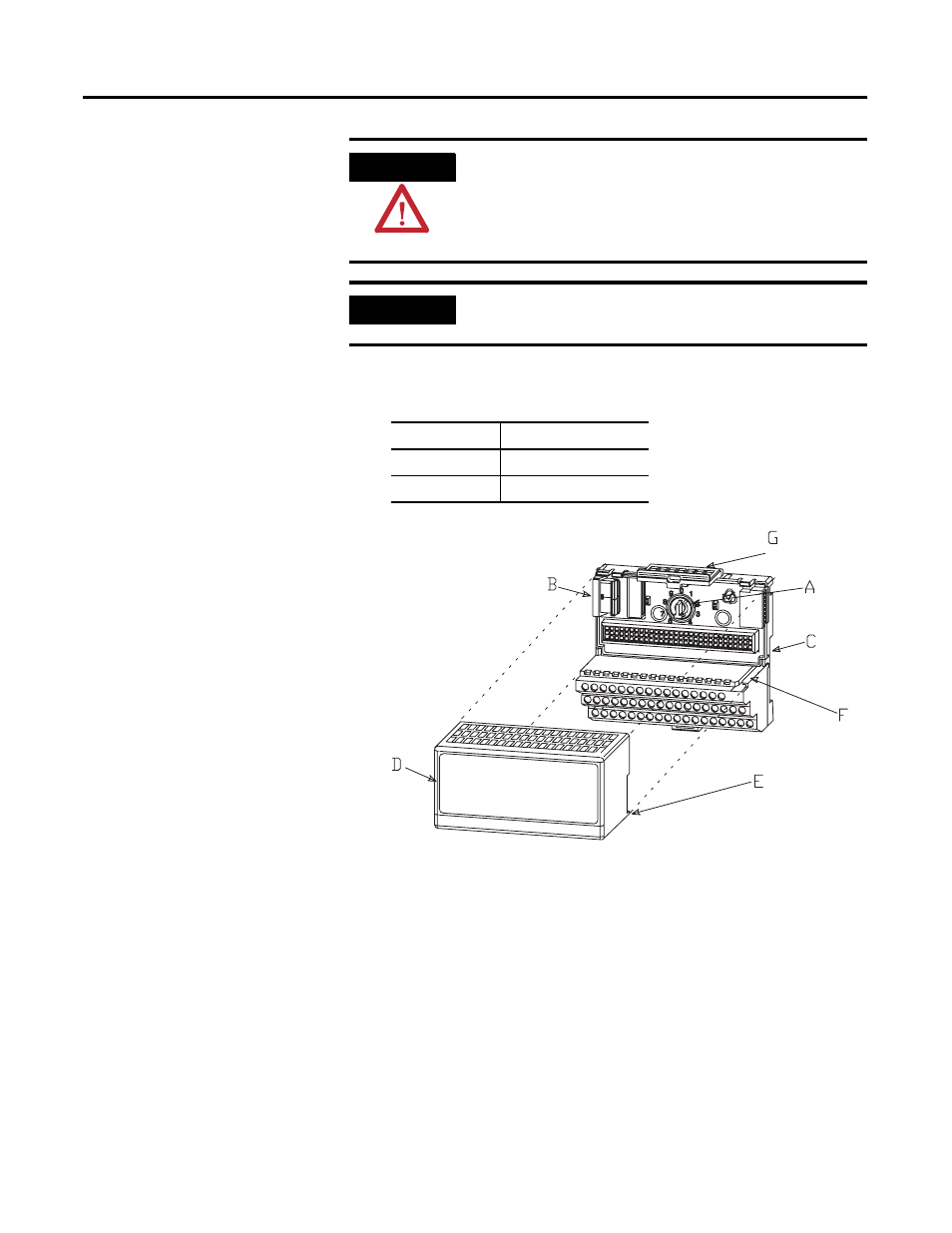
1. Make certain the keyswitch (A) on the terminal base unit (C) is at the
correct position as required for the module.
2. Make certain the side connector (B) is pushed all the way to the left. You
cannot install the module unless the connector is fully extended.
3. Make sure that the pins on the bottom of the module are straight so they
will align properly with the connector in the terminal base unit.
4. Position the module (D) with its alignment bar (E) aligned with the
groove (F) on the terminal base.
5. Press firmly and evenly to seat the module in the terminal base unit. The
module is seated when the latching mechanism (G) is locked into the
module.
6. Repeat the above steps to install the next module in its terminal base.
WARNING
When you insert or remove the XM module while power is
on, an electrical arc can occur. This could cause an
explosion in hazardous location installations. Be sure that
power is removed or the area is nonhazardous before
proceeding.
IMPORTANT
Install the XM-220 overlay slide label to protect serial
connector and electronics when the serial port is not in use.
XM Module
Keyswitch Position
XM-442
6
XM-220
4