Appendix b, Continued – Rockwell Automation SD3000 Drive Configuration, Programming User Manual
Page 87
Appendix B
Continued
Resolver Gain and Balance Variables
The resolver gain and balance variable values are used to compensate for varying lengths of resolver
wiring. The balance value can be generated automatically by commanding the resolver calibration test in
register 101/1 101. The gain value will be generated automatically when the RES_GAN% variable is equal to
zero, i.e., on power-up. Refer to the Power Module Interface Rack manual for more information on the
calibration procedures.
Note that the Distributed Power Systems are designed to be used with the Reliance resolvers described in
the PMI Rack manual. The validity of the results of these calibration procedures are not guaranteed if
resolvers other than those described are used.
l
RES_GAN%
- Resolver Gain
Default Current Value: 0
Low Limit: 0
High Limit: 255
Step:
1
When the value in RES_GAN% is equal to zero, the gain tuning procedure is performed automatically by
the operating system. The default CURRENT value is 0. The value ranges from O-255 counts, with 1 count
representing .1 5 volts of gain. It is recommended that this value be generated using the auto-tuning
procedure because the PMI Processor can take into account the entire resolver circuit when setting the
proper gain value. If the value is adjusted too low, a drive fault will be generated (register 202/1202, bit 8). If
the gain needs to be re-calibrated, reset the value of RES_GAN% to zero. However, do not reset the value
of RES_GAN% to zero while the inner loop is running (i.e., TRQ_ON@ is set) or a drive fault will be
generated (register 202/1 202, bit 8).
l
RES BAL% - Resolver Balance
Default Current Value: 0
Low Limit: 0
High Limit: 79
Step:
1
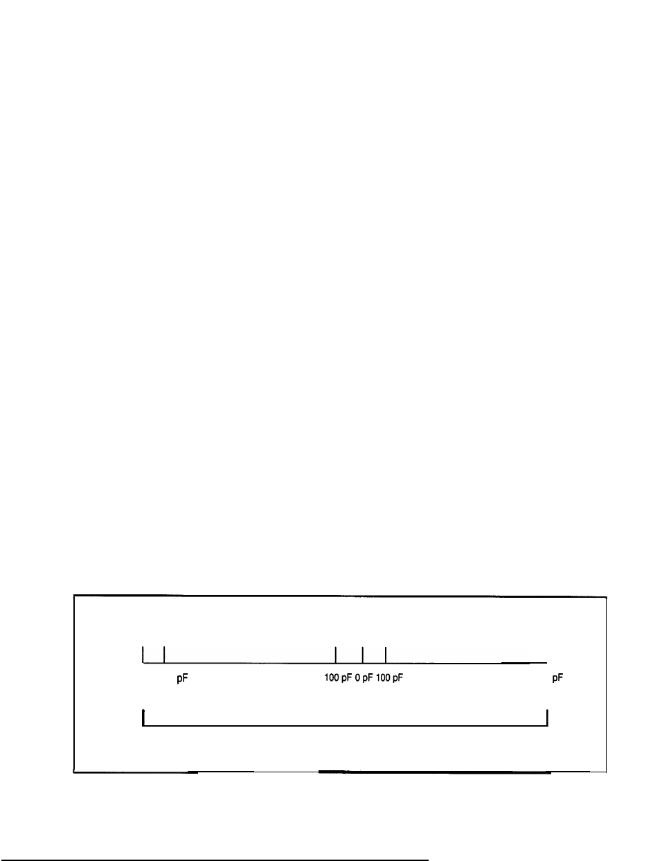
The RES_BAL% local tunable contains the value of the resolver balance, i.e., the amount of capacitance (in
pF) that is to be added to the sine or cosine channel of the resolver to compensate for wiring. Valid values
are from 0 to 79, with 0 representing the fact that balance tuning has not been performed. Values from 1 to
39 add capacitance to the cosine channel, while values from 41 to 79 add capacitance to the sine channel,
Each integer value represents 100 pF as shown in figure B.l .
Tuning
Not Done
0
1
3 9
40 41
7 9
I
3 9 0 0
3 9 0 0
I
Added to Cosine Channel
I I
I
Added to Sine Channel
Figure B-1 - Capacitance Used for Resolver Balancing
B-3