Rockwell Automation SD3000 Drive Configuration, Programming User Manual
Page 26
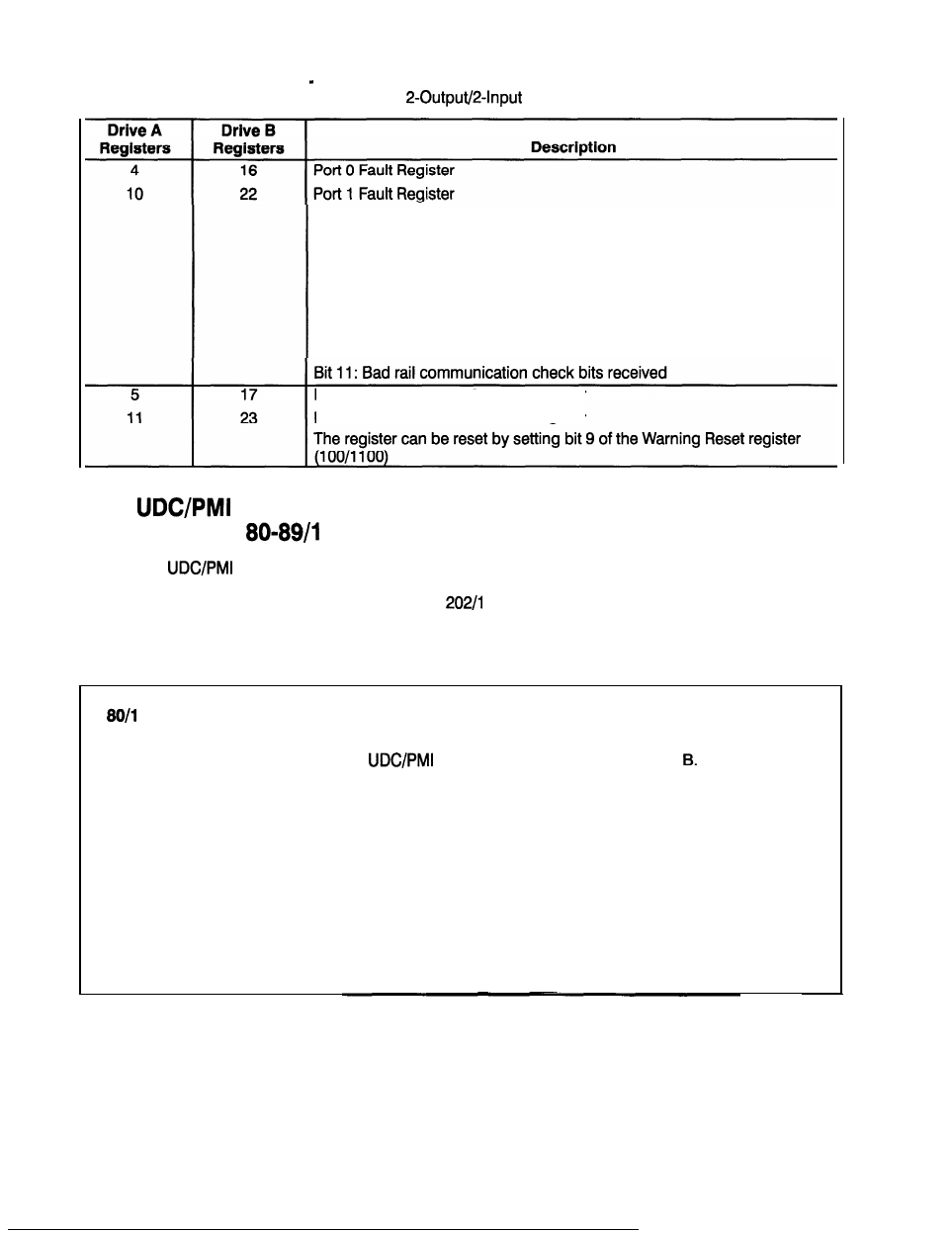
Table 3.6 Fault Register and Check Bit Fault Counter Register
Usage for a
Analog Rail Module
Bit 4: Analog Channel 2 Input Over-Range
Bit 5: Analog Channel 2 Input Under-Range
Bit 6: Analog Channel 3 Input Over-Range
Bit 7: Analog Channel 3 Input Under-Range
Bit 8: No device plugged into a configured port
Bit 9: Bad ID code: device other than a rail is plugged into the port
Bit 10: PMI interface is not ready
Port 0 Check Bit Fault Counter Register
Port 1 Check Bit Fault Counter Register
3.2
Communication Status Registers
(Registers
080-I 089)
The
Communication Registers display the status of the fiber-optic communications
between the UDC module and the PMI. Two consecutive errors will be indicated by a communication
fault and the drive will stop. Refer to register
202, bit 15 for more information. Note that the
communication
status
registers are for system use only and can only be monitored. They cannot be
defined during configuration for access within the application task. The status of these registers will
be retained after a Stop All.
080
UDC Module Ports A/B Status Register
The UDC Module Ports A/B Status register contains bits which describe any errors or warnings re-
ported on the UDC module related to
communication on Port A and Port These bits are
latched when set and will remain set until a fault reset or warning reset is issued.
Bit: 0
Hex Value: 0001
H
Sug. Var. Name:
N/A
Range: N/A
Access:
Read only
UDC Error Code:
N/A
LED:
N/A
Description:
The Invalid Receive Interrupt bit is set when the interrupt generated by the Universal
Serial Controller (USC) is not properly marked. Two consecutive errors of this type will result in a
communication fault.
3-6