2 field power module data screen – Rockwell Automation SD3000 Drive Configuration, Programming User Manual
Page 14
This value is also used to scale the current feedback and may range from 100 to 400%. The
maximum amps produced by the Power Module can be calculated from the following equation:
Maximum Amps* Produced = Amps x Maximum Current Limit
by the Power Module
* Must be less than the Power Module’s output rating or 8000 amps (maximum).
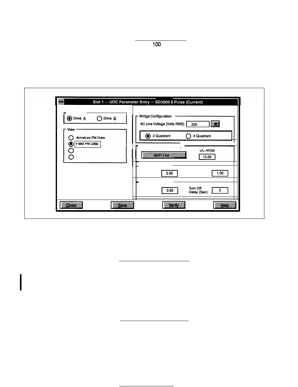
2.2.2 Field Power Module Data Screen
The Field Power Module Data Screen allows you to enter specific information about the 1 -Phase Field
Power Module and motor to be used in your application. See figure 2.3.
UDC Drive
q
Field Power Module Used
Speed Feedback Data
Meter Port Selection
Field Power Module Rating
Motor Field Ratings
Hot Amps:
Minimum Amps:
Field Safety Settings
Field Loss
Trip Amps:
Figure 2.3 - l-Phase Field Power Module Parameter Entry Screen
l
Field Power Module Used
The default setting is that a l-Phase Field Power Module is used. If you are not using a l-Phase
Field Power Module, de-select this option.
Bridge Confiauration Selections
l
A-C Line Voltage (Volts RMS)
Preset voltage values are 230V (default), 380V, or 460V. You can also enter a custom value
(maximum 500V A-C). If an isolation transformer is used in the input power line to the Field Power
Module, enter the voltage from the secondary of the transformer.
l
2 Quadrant or
4
Quadrant
A 2-quadrant, non-regenerative bridge is the default selection. Select the 4-quadrant bridge for
regenerative operation.
Field Power Module Selections
You can enter Power Module ratings either manually or automatically through the W/D list.
l
W/D List
You can choose from a list of wiring diagrams (W/D list) and have the specified default l-Phase
Field Power Module values entered in automatically. Appendix E lists these values.
2-6