Rockwell Automation SD3000 Drive Configuration, Programming User Manual
Page 72
Any UDC dual port register that is to be used in a UDC task must be defined as COMMON in the
task. Recall that UDC dual port memory registers are either reserved for a specific use such as rail
data, or available for application-specific purposes to the programmer. Registers that are not
specifically identified in one of these two ways in the Programming Executive software or in this
instruction manual must not be written to by either the UDC or AutoMax tasks because they are being
used by the operating system.
Generally, the common variables on the UDC module are either written to only by AutoMax tasks
(“read only” to UDC tasks), or they are written to only by a UDC task (“read only” to AutoMax tasks).
The former are typically variables that control an action, e.g., requesting the minor loop to run, and
the latter are typically status variables, e.g., indicating the status of the fiber-optic communication
link.
UDC tasks can access only the UDC module’s own dual port memory. They cannot access other
variables in the rack unless an AutoMax task writes those variable values to the application-specific
registers in the UDC dual port.
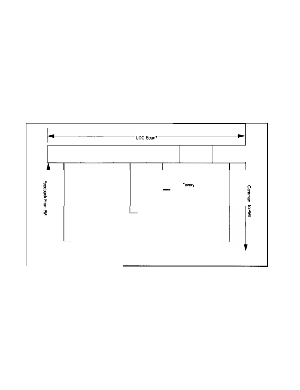
Figure 4.1 illustrates one UDC task scan.
input A
R u n A
Output A
Input B
Run B
Output B
L a t c h
scan”
registers that are
inputs to task B
a
Write “every scan”
registers that are
outputs from task A
Latch “every scan”
registers that are
inputs to task A
Write “every scan”
registers that are
outputs from task B
*Task B can act on Task A outputs within a scan.
Figure 4.1 -Typical UDC Task Scan
All common input values for task A are first read from the dual port memory and then stored in a local
buffer in order to have a consistent context for evaluation. Task A is then executed. After task A has
been executed, the common output values from task A are written from the local memory buffer to
dual port memory. All common input values for task B are then read from dual port memory and
stored in a local buffer in order to have a consistent context for evaluation. Task B is then executed.
Note that task B can act on task A outputs within one scan. After task B has been executed, the
common output values from task B are written from the local memory buffer to dual port memory.
The only exception to this pattern are the common variables in the “Nth” scan application register
area. These registers are updated immediately before every “Nth” scan only, as defined by the user.
See section 4.3 and figure 4.3 for more information on *Nth” scan interrupts. See section 4.2.3 for
more information on the command and feedback messages
4-2