Rockwell Automation SD3000 Drive Configuration, Programming User Manual
Page 62
3.6.2 UDC Module Meter Port Setup Registers (Registers 10014017)
Registers 1001-l 017 are used to configure the UDC module’s meter ports. This configuration
determines what variables from the UDC module’s dual port memory are to be displayed on the
meter ports at the end of the UDC scan. At system power-up, the output values of the ports are reset
to zero.
To map a UDC variable to a specific meter port at power-up, refer to table 3.7 and use the following
procedure. Note that the setup register configurations are retained during a Stop All.
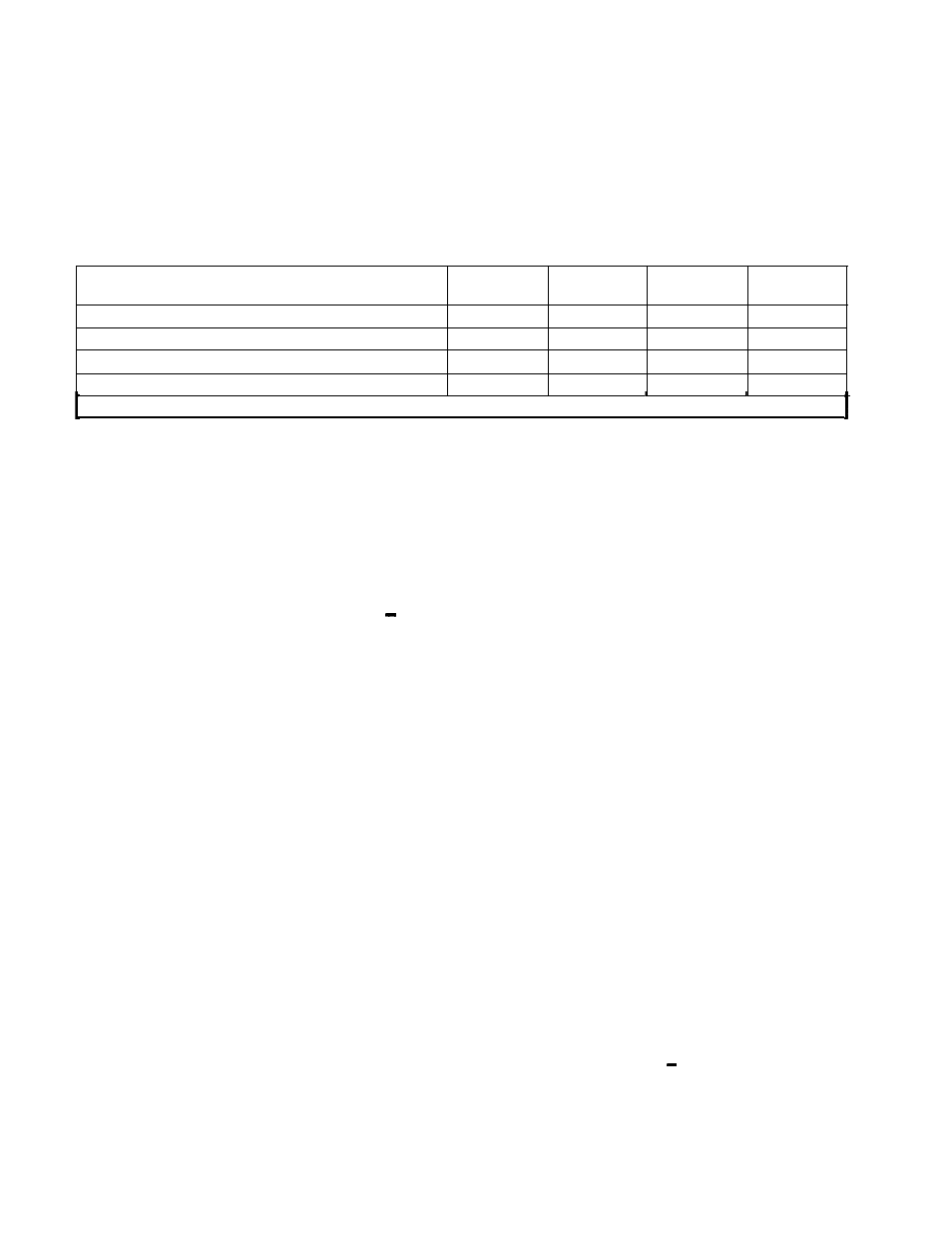
Table 3.7 - UDC Module Meter Port Setup Registers
UDC Module Meter Port Setup Registers
Variable Register Number Register
Bit Number Register
Maximum Value Register
Minimum Value Register
Change Setup Register
Meter
Meter
Port 1
Port 2
1002
1006
1003
1007
1004
1008
1005
1009
Meter
Meter
Port 3
Port 4
1010
1014
1011
1015
1012
1016
1013
1017
I
1001
I
1001
I
1001
I
1001
For each meter port:
Step 1.
Place the register number of the variable you wish to display in the appropriate Variable
Register Number register.
Step 2.
If an individual bit of the register is to be displayed, enter it in the Bit Number register as 100
(bit 00) to 115 (bit 15).
If the entire register is to be displayed, enter a value of zero in the Bit Number register.
Step 3.
Place the value (maximum 32767) that will represent + 1 OV in the Maximum Value register.
Step 4.
Place the value (minimum 32767) that will represent -1 OV in the Minimum Value register.
Step 5.
Set register 1001 (Initiate Change in Setup) equal to a non-zero value to store the new
setup register configurations in memory.
The UDC module’s meter ports are updated once per scan once the UDC task is running and CCLK
is on. They are updated every 5 milliseconds when CCLK is off.
UDC meter ports can also be set up on-line using the “Setup UDC” selection from the Monitor menu
as described in the AutoMax Programming Executive instruction manual. This setup is valid only until
there is a power cycle, in which case the meter ports default to outputting zero voltage and the UDC
Setup screen is cleared on power-up.
Refer to the UDC Module instruction manual (S-3007) for more information about the UDC module’s
meter ports.
3.6.2.1 Resolution of Meter Port Data
For meter ports, the output values will be clamped at the outside (+ 1 0V) limits. Note that if you
select to display a data range that is narrower than the actual range of the data, your output values
will not change until the value returns to within the range you selected to display. In other words, data
is being updated at the rate described above, but the actual output voltage may not change.
If the actual data being sent to the meter port is significantly smaller than the upper and lower limits
assigned by the programmer, the effective resolution of the 8-bit D/A circuit (1 part in 255) will
degrade. To calculate the step change indicated on the meter port, calculate the sum of the absolute
values of the upper and lower limits (the entire range of possible values) assigned to the port. Then
scale this number by 255 in order to determine the minimum step change that will cause the D/A
output to change. For example, suppose the programmer sets the + 1 0V and 1 OV limits at +4095
and -4095, respectively, but the actual value varies only between +1 024 and -1024. Then:
8190/255 = 32 counts
3-42