Rockwell Automation SD3000 Drive Configuration, Programming User Manual
Page 17
0
Armature PM Data
0
Field PM Data
0
Meter Port Selection
Speed Feedback Type
No Speed Feedback
0
Resolver
Analog
Resolver Type
None
xl
x 2
x5
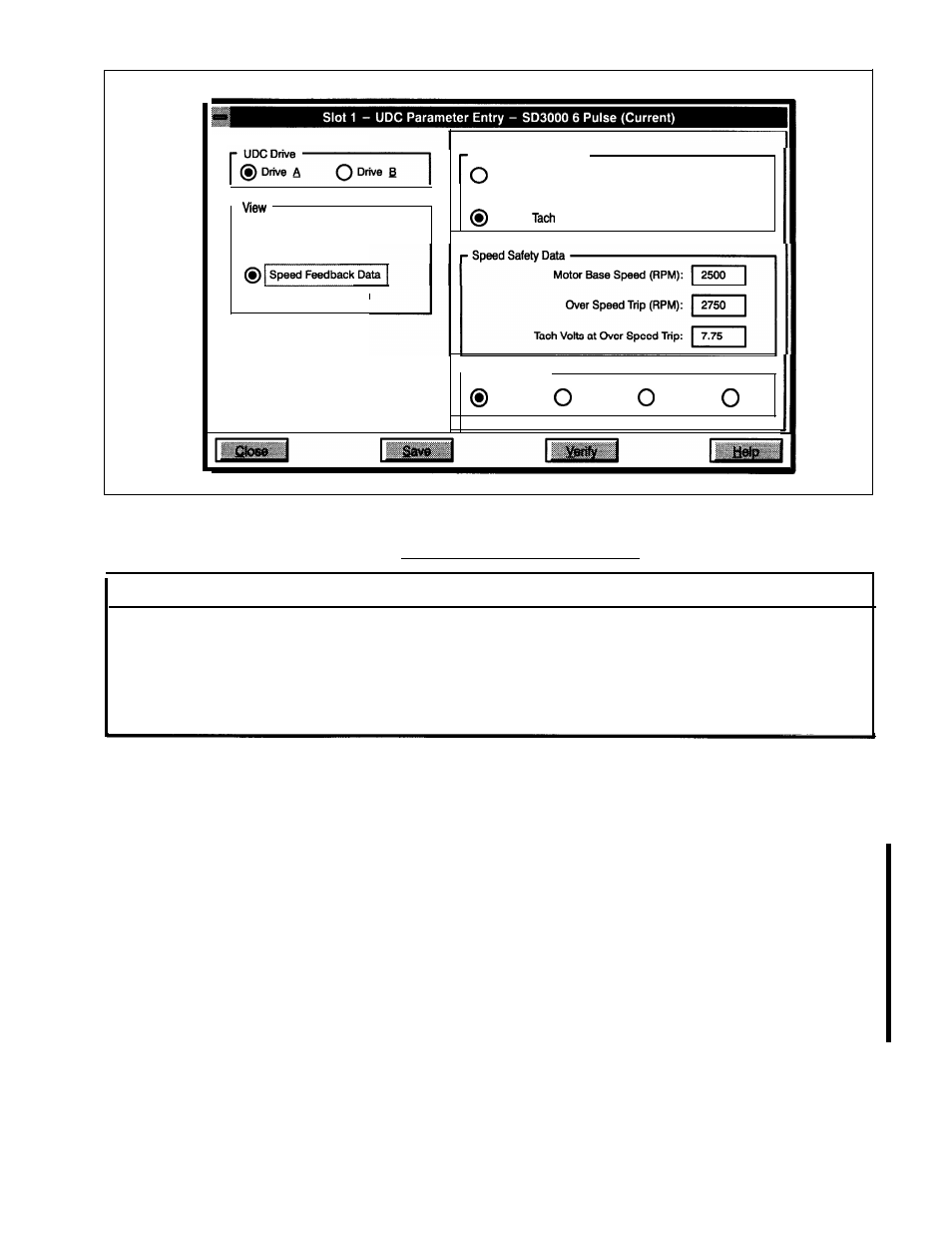
Figure 2.6 - Speed Feedback Parameter Entry Screen With An Analog Tachometer Selected
Speed Feedback Tvpe Selections
W A R N I N G
THE USER MUST ENSURE THAT THE CORRECT FEEDBACK TYPE HAS BEEN SELECTED DURING
CONFIGURATION. IF “NO SPEED FEEDBACK” HAS BEEN SELECTED, THE USER MUST PROVIDE
A N I N D E P E N D E N T M E T H O D O F O F D E T E C T I N G O V E R S P E E D , O T H E R W I S E , A F E E D B A C K L O S S
WILL NOT BE DETECTED, RESULTING IN MOTOR OVERSPEED. FAILURE TO OBSERVE THIS
PRECAUTION COULD RESULT IN BODILY INJURYAND IN DAMAGETO, OR DESTRUCTION OF, THE
EQUIPMENT.
l
No Speed Feedback
If you select No Speed Feedback, which is the default, you do not have to enter Motor Base Speed,
Overspeed Trip Point, or Tach Volts at Over Speed Trip, however, you can select a resolver for
positioning purposes.
Note that if you select No Speed Feedback, the PMI Processor will not perform the Tach Loss and
Over Speed Diagnostics. You must provide an independent method of detecting motor overspeed.
Note also that automatic field weakening will be disabled if you select No Speed Feedback. Refer to
register 100/1 00, bit 11 for more information. Note that when a speed feedback device is used,
overspeed detection is active during auto-tuning.
l
Resolver
If you select Resolver, you must enter the Resolver Type.
l
Analog Tach
If you select Analog Tach, you must enter the Tach Volts at Overspeed Trip Point.
2-9