Rockwell Automation AADvance Controller Demo Unit User Manual
Page 79
Document: 553850 Issue 1.2: March 2011
5-13
TK9_DI_COMPACT and TK9_DI_FULL (Digital Inputs)
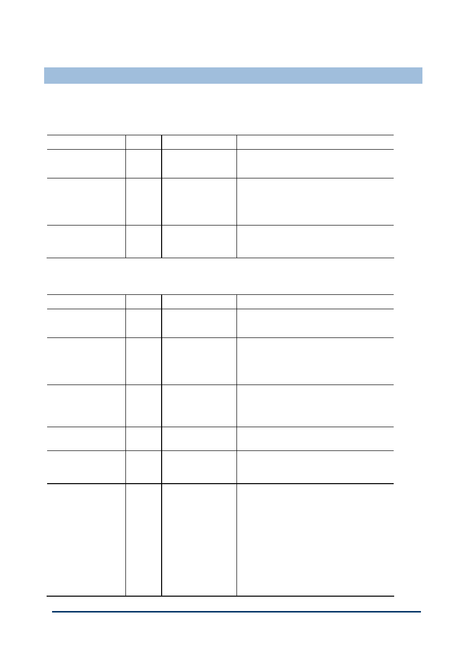
The two data structures for digital input channels (TK9_DI_COMPACT and
TK9_DI_FULL) provide the elements detailed in the tables.
Table 10:
TK9_DI_COMPACT Structure for Digital Inputs
Identifier Type
Description
Remarks
Input
state TRUE: input voltage above threshold T6
FALSE: input voltage below threshold T5
Line
fault
TRUE: input voltage above threshold T8;
between T5 and T4; or below T1
FALSE: input voltage between thresholds T2
and T3; or between T6 and T7
Discrepancy TRUE:
there is a discrepancy in voltage greater
than 20% between the channels of two or
three modules in a redundant configuration (†)
Table 11:
TK9_DI_FULL Structure for Digital Inputs
Identifier Type
Description
Remarks
Input
state TRUE: input voltage above threshold T6
FALSE: input voltage below threshold T5
Line
fault
TRUE: input voltage above threshold T8;
between T5 and T4; or below T1
FALSE: input voltage between thresholds T2
and T3; or between T6 and T7
Discrepancy TRUE:
there is a discrepancy in voltage greater
than 8% (of 24V) between the channels of two
or three modules in a redundant configuration
(†)
BOOL
Channel fault
TRUE: module diagnostics detect a fault in the
channel electronics or firmware (state = 7)
Voltage
Reports
the channel voltage in units of
millivolts and with an accuracy of ± 500mV
(††)
State
Reports
a state value for the channel:
1 = open circuit
2 = de-energized
3 = indeterminate
4 = energized
5 = short-circuit
6 = over voltage
7 = faulted