Rockwell Automation 1440-TPR06-00RE XM-360 Process Module User Manual
Page 40
Publication GMSI10-UM006C-EN-P - August 2010
32 Installing the XM-360 Process Module
Connecting a 4-20mA / 0-20mA Input
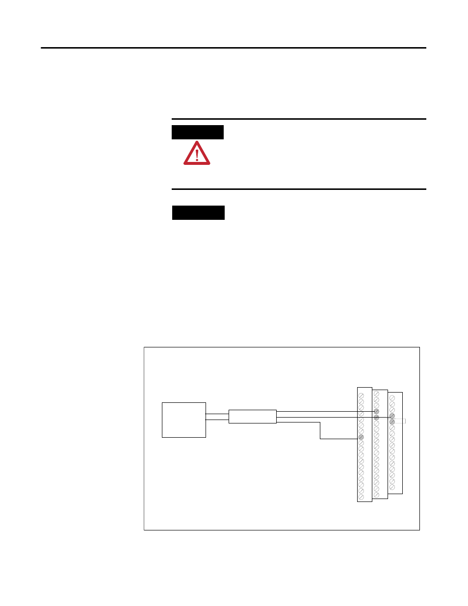
Figures 2.25 to 2.30 show the wiring from a non-loop powered 4-20mA input
to the terminal base unit of the XM-360.
Figure 2.25 Non-loop Powered 4-20mA Input to Channel 1 Wiring
ATTENTION
You may ground the cable shield at either end of the cable.
Do not ground the shield at both ends. Recommended
practice is to ground the cable shield at the XM-360
terminal base and not at the field device. Any convenient
Chassis terminal may be used (see Terminal Block
Assignments on page 17).
TIP
The XM-360 loop-current inputs are low impedance,
approximately 50 ohms. Field devices providing digital
communications (such as HART
®
) on top of their 4-20mA
analog signal may require a minimum loop impedance to
function. This is typically 250 ohms, minimum. If the sum
of the XM-360 input impedance, field wiring impedance,
and other device impedance (such as displays) in the loop
don’t meet this minimum requirement, additional resistance
should be added. Typically this is accomplished by simply
adding a 250 ohm resistor in the loop. Refer to the field
device user manual for details and recommendations.
TYPICAL WIRING FOR NON-LOOP POWERED 4-20mA INPUT
TO XM-360 PROCESS MODULE CHANNEL 1
41
20
19
4-20mA
Transmitter -
+
3
4
RED
BLK
RED
SHIELD
BLK