Inputs & outputs file, Inputs & outputs file -20 – Rockwell Automation 20L, LPM20 PowerFlex 700 Active Converter Power Module User Manual
Page 56
3-20
Programming and Parameters
PowerFlex 700L Active Converter Power Module User Manual
Inputs & Outputs File
Fil
e
Gr
oup No.
Parameter Name & Description
Values
INP
U
TS & OUTPUTS
Mux’
ed T
em
p
s
330
[IGBT NTC Temp1]
Displays the temperature measured in IGBT module 1.
Default:
Min/Max:
Units:
Read Only
-3276.7/+3276.7
0.1°C
331
[IGBT NTC Temp2]
Displays the temperature measured in IGBT module 2.
Default:
Min/Max:
Units:
Read Only
-3276.7/+3276.7
0.1°C
332
[IGBT NTC Temp3]
Displays the temperature measured in IGBT module 3.
Default:
Min/Max:
Units:
Read Only
-3276.7/+3276.7
0.1°C
333
[IGBT NTC Temp4]
Displays the temperature measured in IGBT module 4.
Default:
Min/Max:
Units:
Read Only
-3276.7/+3276.7
0.1°C
334
[Coldplate Temp1]
Displays the temperature measured on the first coldplate.
Default:
Min/Max:
Units:
Read Only
-3276.7/+3276.7
0.1°C
335
[IGBT NTC Temp5]
Displays the temperature measured in IGBT module 5.
Default:
Min/Max:
Units:
Read Only
-3276.7/+3276.7
0.1°C
336
[IGBT NTC Temp6]
Displays the temperature measured in IGBT module 6.
Default:
Min/Max:
Units:
Read Only
-3276.7/+3276.7
0.1°C
337
[IGBT NTC Temp7]
Displays the temperature measured in IGBT module 7.
Default:
Min/Max:
Units:
Read Only
-3276.7/+3276.7
0.1°C
338
[IGBT NTC Temp8]
Displays the temperature measured in IGBT module 8.
Default:
Min/Max:
Units:
Read Only
-3276.7/+3276.7
0.1°C
339
[Coldplate Temp2]
Displays the temperature measured on the second coldplate.
Default:
Min/Max:
Units:
Read Only
-3276.7/+3276.7
0.1°C
Digital I
nputs
350
[Dig In Status]
A set of bits displaying the status of the digital input.
•
Bit 0 (Aux Input) is set when Aux Input is on.
•
Bit 1 (Sel Switch) is set when the DPI SLAVE/MASTER switch on the Active Converter control PCB assembly (
) is in the DPI MASTER position (Stand Alone operation).
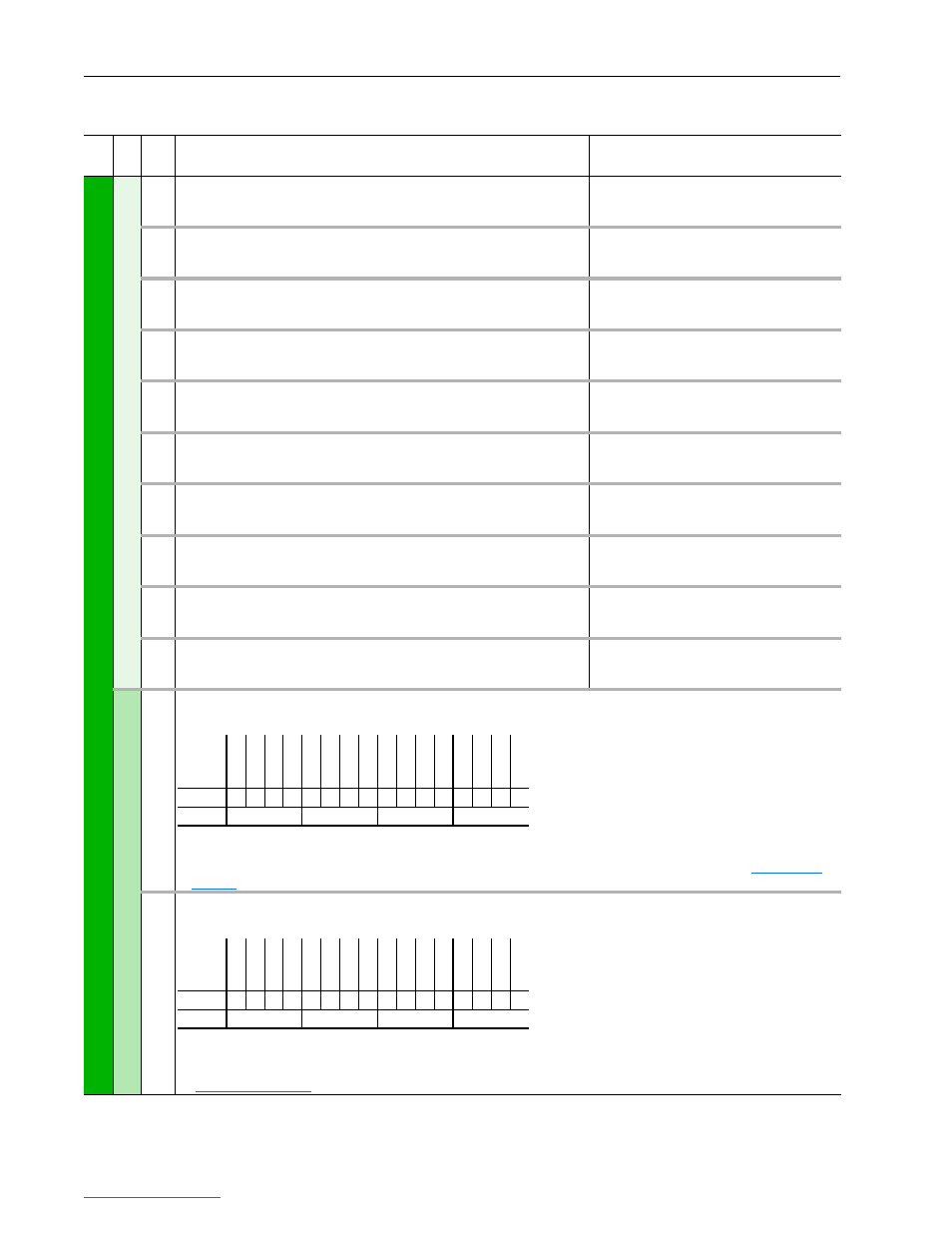
351
[Dig In Frc Mask]
A set of bits to select which input bits are forced.
•
Bit 0 (Aux Input) – Enables forcing of the Aux Input signal. This feature requires a password to operate.
•
Bit 1 (Sel Switch) – Enables forcing of the DPI SLAVE/MASTER switch signal on the Active Converter control PCB assembly
(
). This feature requires a password to operate.
Bit
Definition
Sel Switc
h
Au
x I
np
ut
Default
x
x
x
x
x
x
x
x
x
x
x
x
x
x
0
0
Bit
15 14 13 12 11 10 9
8
7
6
5
4
3
2
1
0
0 = Disabled
1 = Enabled
x = Reserved
Bit
Definition
Sel Switc
h
Au
x I
np
ut
Default
x
x
x
x
x
x
x
x
x
x
x
x
x
x
0
0
Bit
15 14 13 12 11 10 9
8
7
6
5
4
3
2
1
0
0 = Disabled
1 = Enabled
x = Reserved
Read Only