Communication file, Communication file -17 – Rockwell Automation 20L, LPM20 PowerFlex 700 Active Converter Power Module User Manual
Page 53
Programming and Parameters
3-17
PowerFlex 700L Active Converter Power Module User Manual
Communication File
Fil
e
Gr
oup No.
Parameter Name & Description
Values
CO
MM
UN
IC
A
T
ION
Da
talink
s
300
301
[Data In A1] - Link A Word 1
[Data In A2] - Link A Word 2
Parameter number whose value will be written from a communications device data
table.
Default:
Min/Max:
Units:
0 (0 = “Disabled”)
0/399
1
302
303
[Data In B1] - Link B Word 1
[Data In B2] - Link B Word 2
Parameter number whose value will be written from a communications device data
table.
Default:
Min/Max:
Units:
0 (0 = “Disabled”)
0/399
1
304
305
[Data In C1] - Link C Word 1
[Data In C2] - Link C Word 2
Parameter number whose value will be written from a communications device data
table.
Default:
Min/Max:
Units:
0 (0 = “Disabled”)
0/399
1
306
307
[Data In D1] - Link D Word 1
[Data In D2] - Link D Word 2
Parameter number whose value will be written from a communications device data
table.
Default:
Min/Max:
Units:
0 (0 = “Disabled”)
0/399
1
310
311
[Data Out A1] - Link A Word 1
[Data Out A2] - Link A Word 2
Parameter number whose value will be written to a communications device data table.
Default:
Min/Max:
Units:
0 (0 = “Disabled”)
0/399
1
312
313
[Data Out B1] - Link B Word 1
[Data Out B2] - Link B Word 2
Parameter number whose value will be written to a communications device data table.
Default:
Min/Max:
Units:
0 (0 = “Disabled”)
0/399
1
314
315
[Data Out C1] - Link C Word 1
[Data Out C2] - Link C Word 2
Parameter number whose value will be written to a communications device data table.
Default:
Min/Max:
Units:
0 (0 = “Disabled”)
0/399
1
316
317
[Data Out D1] - Link D Word 1
[Data Out D2] - Link D Word 2
Parameter number whose value will be written to a communications device data table.
Default:
Min/Max:
Units:
0 (0 = “Disabled”)
0/399
1
DPI
St
at
us
320
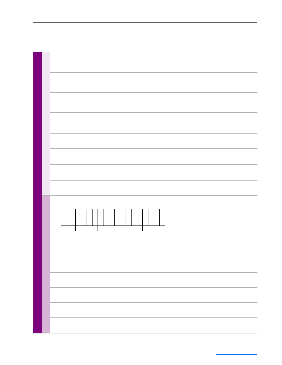
[Connect Status]
A set of bits displaying which DPI communication types are in use by the Converter.
•
Bit 0 (Type 0) is set when Type 0 PC is connected.
•
Bit 3 (Type 3) is set when Type 3 PC is connected.
•
Bit 4 (Type 4) is set when Type 4 PC is connected.
•
Bit 5 (Type 5) is set when Type 5 PC is connected.
•
Bit 6 (Type 6) is set when Type 6 PC is connected.
•
Bit 7 (Type 7) is set when Type 7 PC is connected.
321
[DPI Error Out]
Displays a counter that increments on a DPI error.
Default:
Min/Max:
Units:
Read Only
0/255
None
322
[CS Msg Rx Cnt]
Displays a counter that increments on a Client Server message received.
Default:
Min/Max:
Units:
Read Only
0/65535
None
323
[CS Msg Tx Cnt]
Displays a counter that increments on a Client Server message transmitted.
Default:
Min/Max:
Units:
Read Only
0/65535
None
324
[CS Timeout Cnt]
Displays a counter that increments on a Client Server message time out.
Default:
Min/Max:
Units:
Read Only
0/255
None
Bit
Definition
Ty
pe
7
Ty
pe
6
Ty
pe
5
Ty
pe
4
Ty
pe
3
Ty
pe
0
Default
x
x
x
x
x
x
x
x
0
0
0
0
0
x
x
0
Bit
15 14 13 12 11 10 9
8
7
6
5
4
3
2
1
0
0 = Disabled
1 = Enabled
x = Reserved
Read Only