Rockwell Automation 20L, LPM20 PowerFlex 700 Active Converter Power Module User Manual
Page 54
3-18
Programming and Parameters
PowerFlex 700L Active Converter Power Module User Manual
CO
MM
UN
IC
A
T
ION
DP
I S
ta
tus
325
[CS Msg Bad Cnt]
Displays a counter that increments on a bad Client Server message.
Default:
Min/Max:
Units:
Read Only
0/255
None
326
[PC Msg Rx Cnt]
Displays a counter that increments on a Producer Consumer message received.
Default:
Min/Max:
Units:
Read Only
0/65535
None
327
[PC Msg Tx Cnt]
Displays a counter that increments on a Producer Consumer message transmitted.
Default:
Min/Max:
Units:
Read Only
0/65535
None
328
[PC Timeout Cnt]
Displays a counter that increments on a Producer Consumer message time out.
Default:
Min/Max:
Units:
Read Only
0/255
None
329
[CAN Bus Off Cnt]
Displays a counter that increments on when the CAN Bus is turned off.
Default:
Min/Max:
Units:
Read Only
0/65535
None
M
ask
s & Owners
(1
)
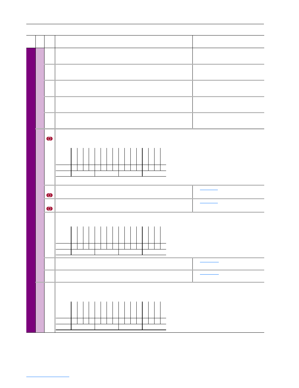
340
[Logic Mask]
Determines which ports can control the drive when parameter 348 - [Write Mask Act] Bit 15
is set to “1.” If the bit for a port is set to “0,” the port will have no control functions except for stop.
The drive must be stopped to change this parameter.
341
[Start Mask]
Controls which adapters can issue start commands.
See
.
342
[Fault Clr Mask]
Controls which adapters can clear a fault.
See
.
343
[Stop Owner]
Displays adapters that are presently issuing a valid stop command.
344
[Start Owner]
Displays adapters that are presently issuing a valid start command.
See
345
[Fault Clr Owner]
Displays adapters that are presently clearing a fault.
See
Security
)
346
[Port Mask Act]
Bits 0-6 indicate status for DPI port communication.
Bit 15 indicates when security software is controlling the parameter.
Fil
e
Gr
oup No.
Parameter Name & Description
Values
Bit
Definition
DPI P
or
t 6
DPI P
or
t 5
DPI P
or
t 4
DPI P
or
t 3
DPI P
or
t 2
DPI P
or
t 1
Default
x
x
x
x
x
x
x
x
x
1
1
1
1
1
1
x
Bit
15 14 13 12 11 10 9
8
7
6
5
4
3
2
1
0
0 = Control Masked
1 = Control Permitted
x = Reserved
Bit
Definition
DP
I P
or
t 6
DP
I P
or
t 5
DP
I P
or
t 4
DP
I P
or
t 3
DP
I P
or
t 2
DP
I P
or
t 1
Default
x
x
x
x
x
x
x
x
x
0
0
0
0
0
0
x
Bit
15 14 13 12 11 10 9
8
7
6
5
4
3
2
1
0
0 = No Command
1 = Issuing Command
x = Reserved
Bit
Definition
Secu
ri
ty
DPI P
or
t 6
DPI P
or
t 5
DPI P
or
t 4
DPI P
or
t 3
DPI P
or
t 2
DPI P
or
t 1
Host
Default
0
x
x
x
x
x
x
x
x
1
1
1
1
1
1
1
Bit
15 14 13 12 11 10 9
8
7
6
5
4
3
2
1
0
0 = Not Active
1 = Active
x = Reserved
Read Only
Read Only