Rockwell Automation 20L, LPM20 PowerFlex 700 Active Converter Power Module User Manual
Page 44
3-8
Programming and Parameters
PowerFlex 700L Active Converter Power Module User Manual
COMMAND
Data Exc
h
ange
071
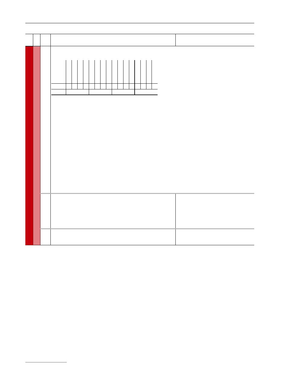
[Converter Status]
A set of bits sent from the Converter to the Inverter to indicate status.
•
Bit 0 (Cnvtr Ready) is set by the Converter when all inhibits are cleared.
•
Bit 1 (Ac Line Sync) is set by the Converter when it is synchronized to the AC line.
•
Bit 2 (Pchg Closed) indicates the status of the precharge bypass contactor.
•
Bit 3 (Cnvtr Active) is set by the Converter when it is regulating.
•
Bit 4 (Bus Reg Ena) is set by the Converter to enable the Inverter bus voltage regulator.
•
Bit 5 (Ac Ride Thru) is set by the Converter during a power dip ride through.
•
Bit 6 (Active I Lmt) is set by the Converter when active current is limited.
•
Bit 7 (kVAR Lmt) is set by the Converter when the requested KVAR is limited.
•
Bit 8 (Regenerating) is set by the Converter when it is regenerating power to the AC line.
•
Bit 9 (PWM SyncLock) is set by the Converter when the PWM carrier is locked to the external synchronization signal.
•
Bit 10 (CML Comm Ok) is set by the Converter when a valid External CML reference is received.
•
Bit 11 (Abort Decel) is set when the DC link drops below the voltage when the precharge must open. This signals the Inverter to
stop regulating the bus voltage by decelerating the motor and beginning a coast to stop.
•
Bit 14 (Cnvtr Alarm) is set by the Converter when it has detected an alarm.
•
Bit 15 (Cnvtr Fault) is set by the Converter when it has detected a fault.
072
[Converter Min Vdc]
Sets the minimum DC Link voltage required by the Inverter for the present
operating conditions. This value is calculated as (motor voltage * 1.44) and then
transferred to the Converter by Type 3 communication. This is used when the
voltage to the motor needs to be greater than the peak of the AC line voltage.
Under low line conditions, the Converter can boost the DC Link voltage above
the peak of the AC line.
Default:
Min/Max:
Units:
0.0 Vdc
0.0/1225.0 Vdc
0.1 Vdc
073
[Converter Fault]
This parameter is used to pass a fault code from the Converter to the Inverter so
all Converter fault codes are logged in the Inverter’s fault queue.
Default:
Min/Max:
Units:
0
0/399
None
Fil
e
Gr
oup No.
Parameter Name & Description
Values
Bit
Definition
Cn
vt
r F
ault
Cn
vtr Alar
m
Abor
t Decel
CML C
omm Ok
PW
M Sy
ncLo
ck
Regen
er
at
ing
kV
AR L
m
t
Ac
tiv
e I Lmt
Ac Rid
e Thr
u
Bus Reg Ena
Cn
vtr Ac
tiv
e
Prec
hg Close
d
Ac Line Sync
Cn
vtr Rea
dy
Default
0
0
x
x
0
0
0
0
0
0
0
0
0
0
0
0
Bit
15 14 13 12 11 10 9
8
7
6
5
4
3
2
1
0
0 = Disabled
1 = Enabled
x = Reserved
Read Only