Attach motor cables – Rockwell Automation MPAR Electric Cylinders User Manual
Page 11
MP-Series Electric Cylinders 11
Rockwell Automation Publication MPAR-IN001D-EN-P - September 2012
Attach Motor Cables
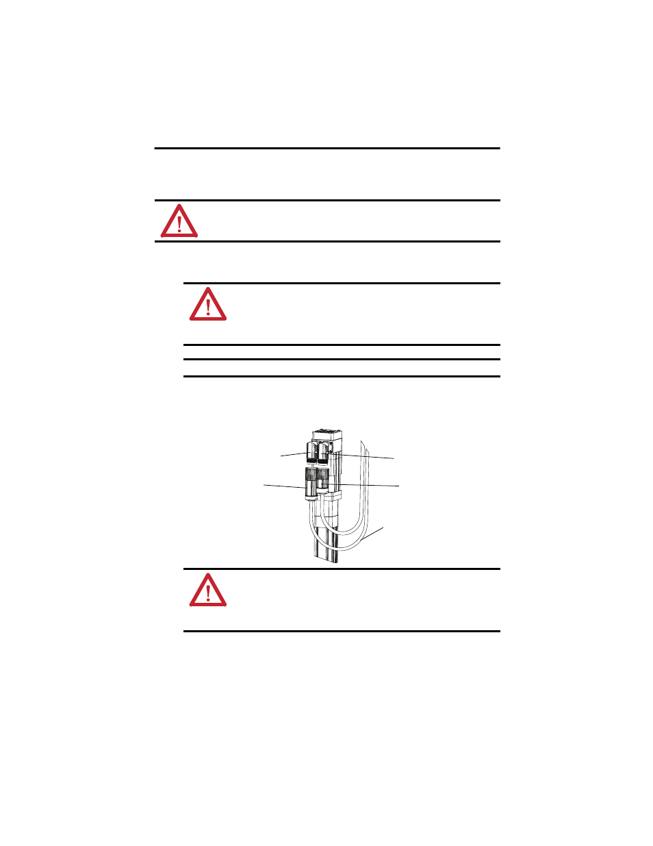
Follow these steps to attach the power and feedback cables after the electric-cylinder is mounted.
1.
Carefully align each cable connector with the respective motor connector as shown in
the following diagram.
2.
Fully seat the feedback connector and the power/brake connector and hand tighten the
collar one-quarter turn.
3.
Form a drip loop in the cable to keep liquids away from the connectors.
4.
Verify the continuity and functionality of the thermal switch signals, TS+ and TS-.
These signals are transmitted through the feedback cable that connects the motor to its
controlling drive.
ATTENTION: Consider electric-cylinder surface temperature when selecting motor-mating
connections and cables.
Failure to observe these safety precautions can result in personal injury or damage to equipment.
ATTENTION: Keyed connectors must be properly aligned and hand-tightened the
recommended number of turns.
Improper connector alignment is indicated by the need for excessive force, such as the
need for the use of tools, to fully seat connectors.
Failure to observe these safety precautions can result in damage to equipment.
IMPORTANT
Remove the O-ring from the motor connector.
ATTENTION: Make sure that cables are installed and restrained to prevent uneven
tension or flexion at the cable connectors. Excessive and uneven lateral force at the cable
connectors may result in the connector’s environmental seal opening and closing as the
cable flexes. Failure to observe these safety precautions can result in damage to the
electric-cylinder motor and its components.
Flat Surface
with Logo on Top
Top of connector is relative to motor orientation.
Feedback Connector
Drip Loop
Power Connector
Flat Surface
with Logo on Top