Alarm deadband – Rockwell Automation 1769-IF16V Compact High Density Analog Input Modules User Manual
Page 45
Publication 1769-UM018A-EN-P - October 2008
45
Module Data, Status, and Channel Configuration Chapter 3
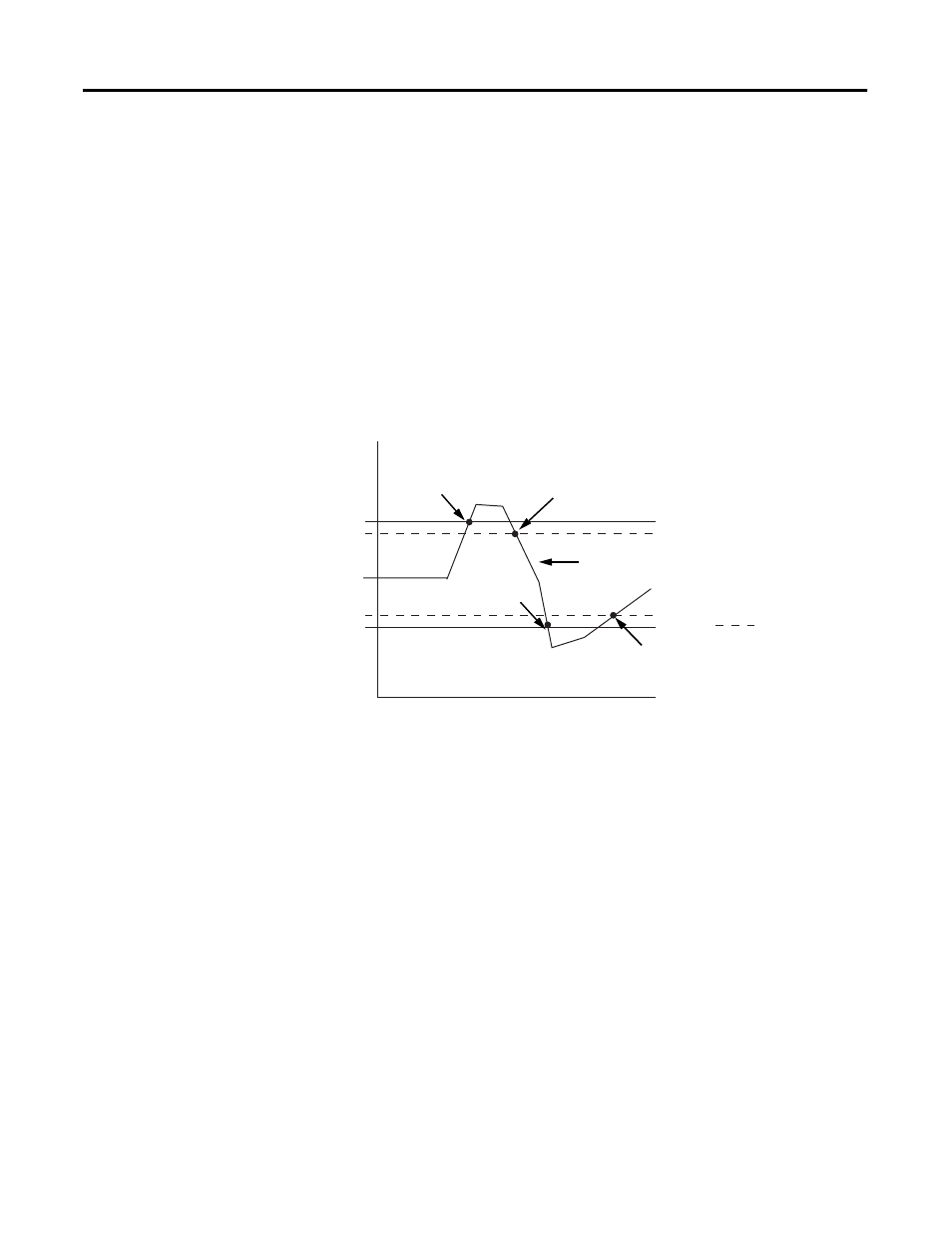
Alarm Deadband
You may configure an alarm deadband to work with the process
alarms. The deadband lets the process alarm status bit remain set,
despite the alarm condition disappearing, as long as the input data
remains within the deadband of the process alarm.
This illustration shows an example of input data that sets each of the
two alarms at some point during module operation. In this example,
latching is disabled; therefore, each alarm turns OFF when the
condition that caused it to set ceases to exist and the input data clears
the alarm deadband regions.
Alarm Deadbands
The module checks for an alarm deadband value that is less than 0 or
large enough to be equal to or exceed one-half of the difference
between the High alarm and Low alarm values. When one of these
conditions occurs, a module configuration fault results.
Low
High
Alarm Deadbands
Normal Input Range
High alarm turns OFF.
Low alarm turns OFF.
Low alarm turns ON.
High alarm turns ON.