Rockwell Automation 1769-IF16V Compact High Density Analog Input Modules User Manual
Page 22
22
Publication 1769-UM018A-EN-P - October 2008
Chapter 2 Installation and Wiring
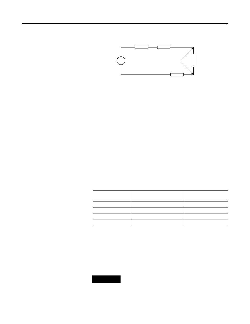
Voltage Input Accuracy
Where:
Rc = DC resistance of the cable (each conductor) depending on
cable length
Rs = Source impedance of analog transducer/sensor input
Ri = Impedance of the voltage input (1 M
Ω
for 1769-IF16V module)
Vs = Voltage source (voltage at the transducer/sensor input device)
Vin = Measured potential at the module input
%Ai = Percent added inaccuracy in a voltage-based system due
to source and cable impedance.
For example, for Belden 8761 two conductor, shielded cable:
Rc = 16
Ω
/1000 ft
Rs = 0 (ideal source)
As input source impedance (Rs) and/or resistance (DC) of the cable
(Rc) get larger, system accuracy decreases. If you determine that the
inaccuracy error is significant, implementing the following equation in
the control program can compensate for the added inaccuracy error
due to the impedance of the source and cable.
V in
Vs
Ri
Rc
Rc
Rs
+
-
Table 2.1 Effect of Cable Length on Input Accuracy
Length of Cable,
m (ft)
DC Resistance of the Cable,
Rc (
Ω
)
Accuracy Impact at the
Input Module
50 (164)
2.625
0.000525%
100 (328)
5.25
0.00105%
200 (656)
10.50
0.0021%
300 (984)
15.75
0.00315%
TIP
For the 1769-IF16C module, source and cable impedance do not
impact system accuracy.
Vin
Ri
Vs
×
[
]
Rs
2
Rc
×
(
)
Ri
+
+
[
]
--------------------------------------------------------
=
%
Ai
1
Vin
Vs
---------
–
⎝
⎠
⎛
⎞
100
×
=
Vs
Vin
Rs
2
Rc
×
(
)
Ri
+
+
[
]
Ri
--------------------------------------------------------
Ч
=