Rockwell Automation 1769-IF16V Compact High Density Analog Input Modules User Manual
Page 26
26
Publication 1769-UM018A-EN-P - October 2008
Chapter 2 Installation and Wiring
3. At one end of the cable, twist the drain wire and foil shield
together.
Under normal conditions, this drain wire and shield junction
must be connected to earth ground, via a panel or DIN rail
mounting screw at the analog I/O module end. Keep the length
of the drain wire as short as possible.
In environments where high frequency noise may be present, it
may be necessary to also ground the cable shields to earth via a
0.1 µF capacitor at the sensor end.
4. At the other end of the cable, cut the drain wire and foil shield
back to the cable, unless the sensor end of the cable requires
the shields to be connected to earth ground via the capacitor
described in step 3.
5. Connect the signal wires to the terminal block.
6. Connect the other end of the cable to the analog input or output
device.
7. Repeat steps 1…5 for each channel on the module.
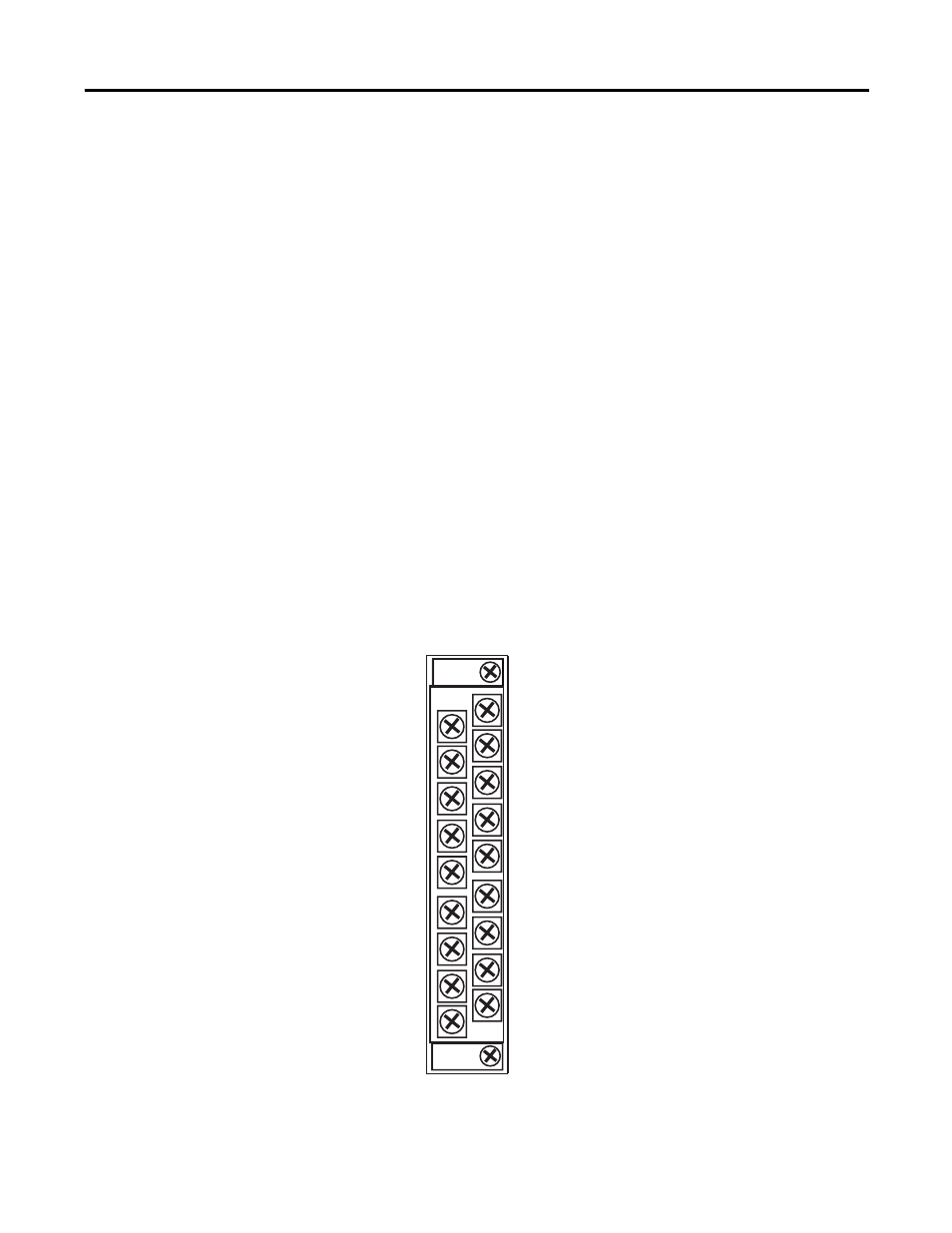
Terminal Layout
IN15+
IN13+
IN11+
IN9+
COM
IN7+
IN5+
IN3+
IN1+
IN14+
IN12+
IN10+
IN8+
COM
IN6+
IN4+
IN2+
IN0+