Wire the modules – Rockwell Automation 1769-IF16V Compact High Density Analog Input Modules User Manual
Page 25
Publication 1769-UM018A-EN-P - October 2008
25
Installation and Wiring Chapter 2
Wire the Modules
After the analog module is properly installed, follow the wiring
procedure below. To ensure proper operation and high immunity to
electrical noise, always use Belden 8761 (shielded, twisted-pair) or
equivalent wire.
Belden 8761 Wire
To wire your module, follow these steps.
1. At each end of the cable, strip some casing to expose the
individual wires.
2. Trim the signal wires to 2-inch lengths. Strip about 5 mm
(3/16 in.) of insulation away to expose the end of the wire.
ATTENTION
To prevent shock hazard, care should be taken when wiring the
module to analog signal sources. Before wiring any analog
module, disconnect power from the system power supply and
from any other source to the analog module.
ATTENTION
When wiring an analog input, take care to avoid connecting a
voltage source to a channel configured for current input.
Improper module operation or damage to the voltage source
can occur.
Never connect a voltage or current source to an analog output
channel.
ATTENTION
Be careful when stripping wires. Wire fragments that
fall into a module could cause damage when you cycle
power.
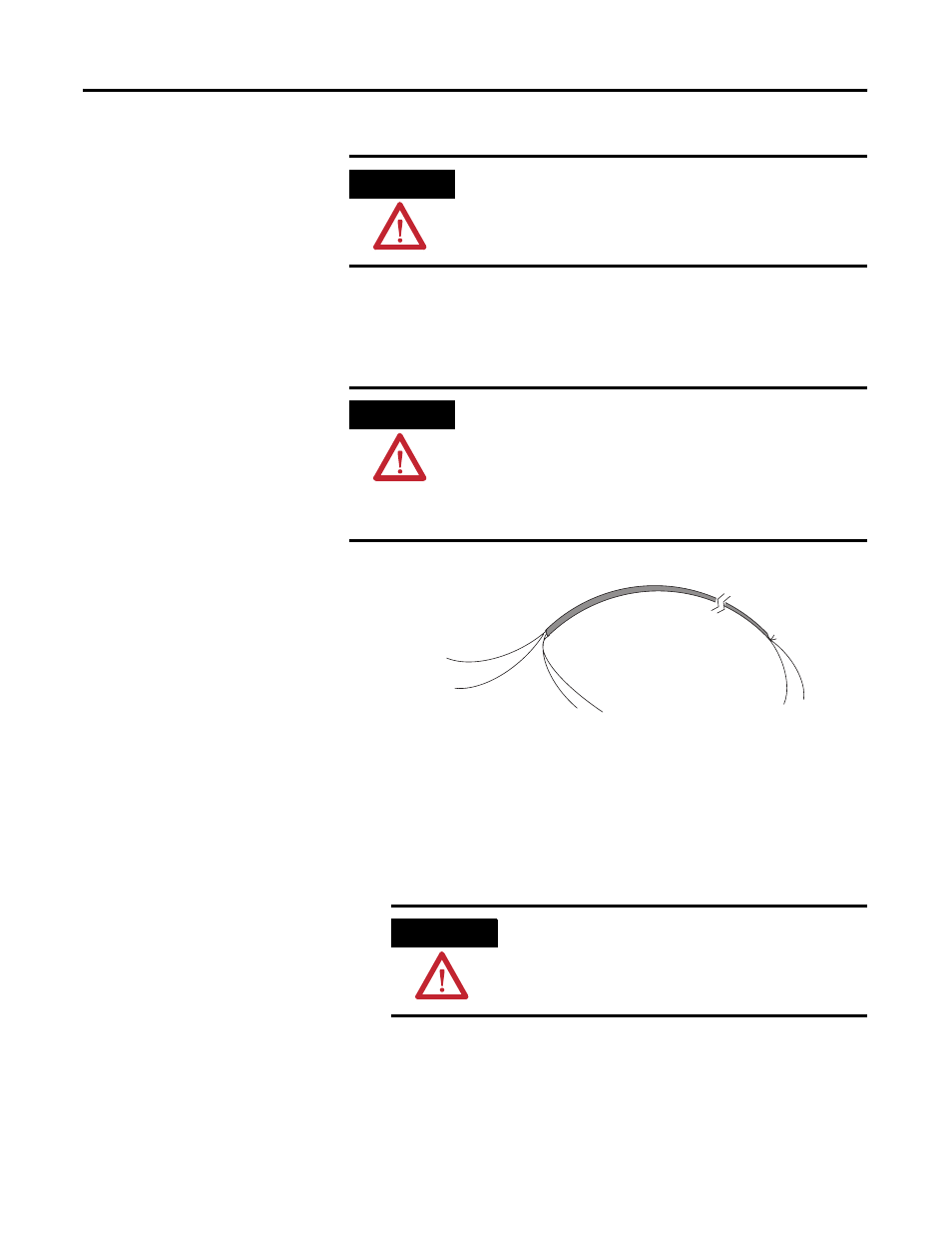
Cable
Signal Wire
Signal Wire
Drain Wire
Foil Shield
Signal Wire
Signal Wire
Cut foil shield
and drain wire.