Channel configuration -2, Channel configuration – Rockwell Automation 1746-NT4 Series B,D17466.6.1 SLC 500 4-Channel Thermocouple/mV Input Module User Manual User Manual
Page 88
Publication 1746-UM007C-EN-P - July 2004
8-2 Application Examples
Channel Configuration
Configure the thermocouple channel with the following setup:
•
type J thermocouple
•
°F - display to whole degree
•
zero data word in the event of an open circuit
•
10 Hz input filter to reject high frequency noise and give good
rejection of 60 Hz line noise
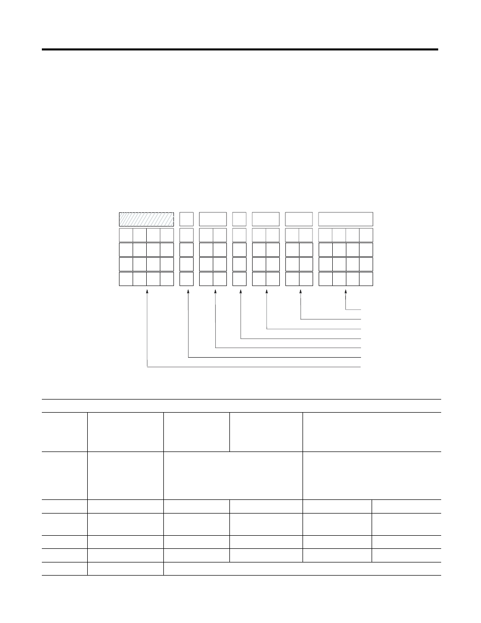
Channel Configuration Worksheet (With Settings Established for Channel 0)
Input Type Select
Data Format Select
Open Circuit Select
Temperature Units Select
Filter Frequency Select
Channel Enable
Not Used
Channel 0
Channel 1
Channel 2
Channel 3
11
0
0
1
0
0
0
0
9
10
8
1
6
7
0
0
0
1
4
5
0
0
0
0
0
1
2
3
0
0
0
0
0
0
0
0
0
0
0
0
Bit Number
12
13
14
15
•
•
•
•
•
•
•
Bits:
0-3
Input Type Select
0000 = J
0001 = K
0010 = T
0011 = E
0100 = R
0101 = S
0110 = B
0111 = N
1000 = ±50 mV
1001 = ±100 mV
1111 = CJC temperature
4 and 5
Data Format Select
00 = engineering units, x1 (0.1°/step,
0.01 mV/step)
01 = engineering units, x10 (1°/step,
0.1 mV/step)
10 = scaled-for-PID (0 to 16383)
11 = proportional counts (-32768 to +32767)
6 and 7
Open Circuit Select
00 = zero
01 = upscale
10 = downscale
8
Temperature Units
Select
0 = degrees Celsius
1 = degrees Fahrenheit
9 and 10
Filter Frequency Select
00 = 10 Hz
01 = 50 Hz
10 = 60 Hz
11 = 250 Hz
11
Channel Enable
0 = channel disabled
1 = channel enabled
12-15
Not Used
0000 = always make this setting