Input circuit block diagram – Rockwell Automation 1746-NT4 Series B,D17466.6.1 SLC 500 4-Channel Thermocouple/mV Input Module User Manual User Manual
Page 18
Publication 1746-UM007C-EN-P - July 2004
1-6 Overview
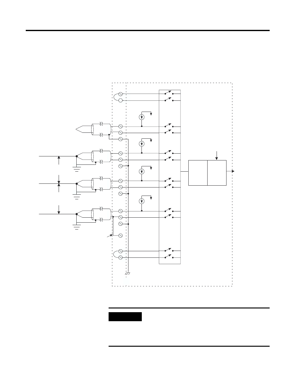
Input Circuit Block Diagram
Input Circuit Block Diagram
Digital
Value
User-Selected
Filter Frequency
Digital
Filter
Analog to
Digital
Convertor
Multiplexer
Open Circuit
Detection
+
-
Shield
+
-
+
-
Shield
+
-
Shield
+
-
+
-
CJCA Sensor
CJCB Sensor
Terminal Block
Module Circuitry
Chassis Ground
(internally connected)
Channel 1
+
-
Shield
user supplied
jumper
grounded
thermocouple
Channel 2
within
2V*
grounded
thermocouple
Channel 3
Channel 0
within
2V*
grounded
thermocouple
ungrounded
thermocouple
Analog
Common
*See Important note below
.
IMPORTANT
When using multiple grounded and/or exposed
thermocouples that are touching on electrically
conductive material with Series B or higher
1746-NT4, the ground potential between any two
channels cannot exceed 2 volts.