Wiring input devices to the nt4 -11, Wiring input devices to the nt4 – Rockwell Automation 1746-NT4 Series B,D17466.6.1 SLC 500 4-Channel Thermocouple/mV Input Module User Manual User Manual
Page 39
Publication 1746-UM007C-EN-P - July 2004
Installation and Wiring 3-11
Wiring Input Devices to the NT4
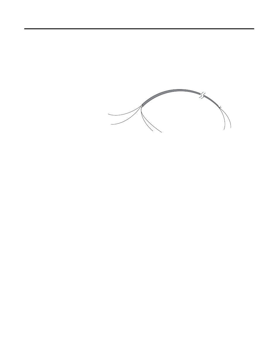
After the thermocouple module is properly installed in the chassis,
follow the wiring procedure below using the proper thermocouple
extension cable, or Belden 8761 for non-thermocouple applications.
To wire your NT4 module:
1. At each end of the cable, strip some casing to expose the
individual wires.
2. Trim the signal wires to 2-inch lengths. Strip about 3/16 inch
(4.76 mm) of insulation away to expose the end of the wire.
3. At one end of the cable twist the drain wire and foil shield
together, bend them away from the cable, and apply shrink
wrap. Then earth ground at the preferred location based on the
type of sensor you are using (see Wiring Considerations).
4. At the other end of the cable, cut the drain wire and foil shield
back to the cable and apply shrink wrap.
5. Connect the signal wires to the NT4 terminal block and the
input.
6. Repeat steps 1 through 6 for each channel on the NT4 module.
Foil Shield
Drain Wire
(Twist together, shrink wrap,
and connect to earth ground.)
Signal Wire
Signal Wire
Signal Wire
Signal Wire
(Cut foil shield and
drain wire; then
insulate at cable end.)
Cable