Wiring considerations -8, Wiring considerations – Rockwell Automation 1746-NT4 Series B,D17466.6.1 SLC 500 4-Channel Thermocouple/mV Input Module User Manual User Manual
Page 36
Publication 1746-UM007C-EN-P - July 2004
3-8 Installation and Wiring
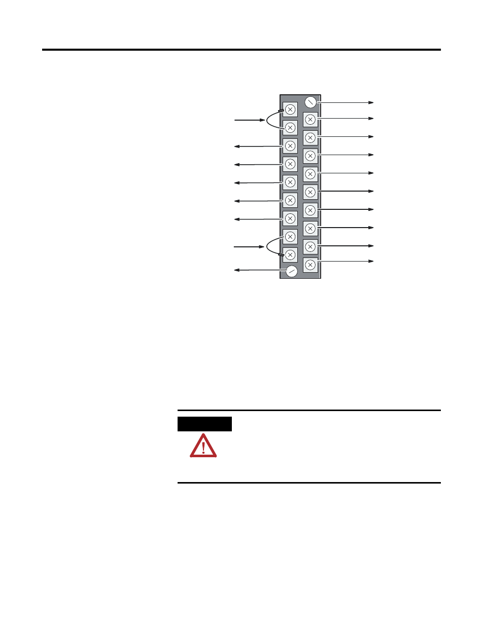
Replacing a Series A thermocouple module with a Series B module
requires that the bottom right terminal (which was SHIELD on Series A
modules) no longer be connected to CHASSIS GROUND if it was
previously. Use one of the other SHIELD terminals.
Wiring Considerations
Follow the guidelines starting below when planning your system
wiring.
•
To limit noise, keep thermocouple and millivolt signal wires as
far away as possible from power and load lines.
ATTENTION
The possibility exists that grounded or exposed
thermocouples can become shorted to a potential
greater than that of the thermocouple itself. Due to
possible shock hazard, care should be taken when
wiring these types of thermocouples. Refer to
Appendix D for more details.
Channel 0+
Channel 0
Shield
Channel 1+
Channel 1
Shield
Channel 2+
Channel 2
Shield
Channel 3+
Channel 3
Shield
Analog Common
Shield
CJC A
CJC A+
CJC B+
CJC B
(Terminal Block Spare Part Catalog Number 1746-RT32)
Release Screw
Release Screw
CJC Assembly
CJC Assembly
[see below]
_
_
_
_
_
_