System overview, General diagnostic features -3, System overview -3 – Rockwell Automation 1746-NT4 Series B,D17466.6.1 SLC 500 4-Channel Thermocouple/mV Input Module User Manual User Manual
Page 15: General diagnostic features
Publication 1746-UM007C-EN-P - July 2004
Overview 1-3
General Diagnostic Features
The thermocouple/mV module contains diagnostic features that can
help you identify the source of problems that may occur during
power-up or during normal channel operation. These power-up and
channel diagnostics are explained in chapter 7, Module Diagnostics
and Troubleshooting.
System Overview
The thermocouple module communicates to the SLC 500 processor
through the parallel backplane interface and receives +5V dc and
+24V dc power from the SLC 500 power supply through the
backplane. No external power supply is required. You may install as
many thermocouple modules in your system as the power supply can
support.
Hardware
Function
Channel Status LED
Indicators
Display operating and fault status of
channels 0, 1, 2, and 3
Module Status LED
Displays module operating and fault status
Side Label (Nameplate)
Provides module information
Removable Terminal Block
Provides physical connection to input devices.
It is color coded green.
Door Label
Permits easy terminal identification
Cable Tie Slots
Secure and route wiring from module
Self-Locking Tabs
Secure module in chassis slot
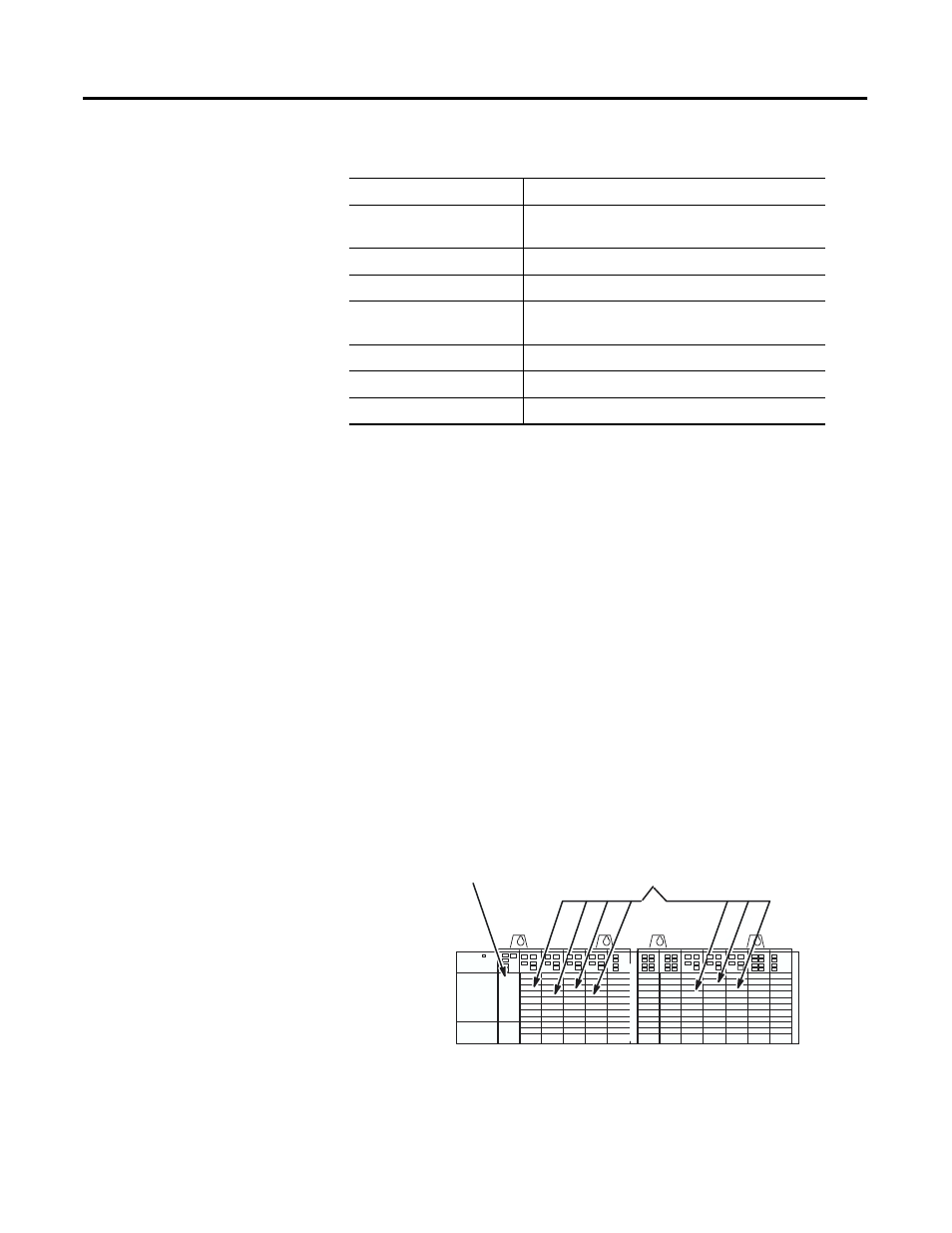
Thermocouple Modules
SLC Processor