Module installation and removal, General considerations -5, Module installation and removal -5 – Rockwell Automation 1746-NT4 Series B,D17466.6.1 SLC 500 4-Channel Thermocouple/mV Input Module User Manual User Manual
Page 33: General considerations
Publication 1746-UM007C-EN-P - July 2004
Installation and Wiring 3-5
General Considerations
Most applications require installation in an industrial enclosure to
reduce the effects of electrical interference. Thermocouple inputs are
highly susceptible to electrical noises due to the small amplitudes of
their signal (microvolt/°C).
Group your modules to minimize adverse effects from radiated
electrical noise and heat. Consider the following conditions when
selecting a slot for the thermocouple module. Position the module:
•
in a slot away from sources of electrical noise such as
hard-contact switches, relays, and AC motor drives
•
away from modules which generate significant radiated heat,
such as the 32-point I/O modules
In addition, route shielded twisted pair thermocouple or millivolt
input wiring away from any high voltage I/O wiring.
Module Installation and
Removal
When installing the module in a chassis, it is not necessary to remove
the terminal block from the module. However, if the terminal block is
removed, use the write-on label located on the side of the terminal
block to identify the module location and type.
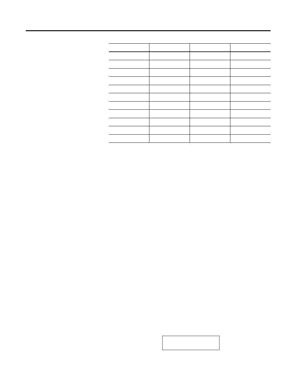
NO4V
x
0.055
0.145
ITB16
x
0.085
N/A
ITV16
x
0.085
N/A
IC16
x
0.085
N/A
KE
x
0.150
0.040
KEn
x
0.150
0.145
OBP16
x
0.250
N/A
OVP16
x
0.250
N/A
NT4
x
0.060
0.040
NR4
x
0.050
0.050
HSTP1
x
0.020
N/A
1746-
NT4
5V dc Amps
24V dc Amps
SLOT ____ RACK ____
•
MODULE _______________