Hardware features -2, Hardware features, Cable tie slots – Rockwell Automation 1746-NT4 Series B,D17466.6.1 SLC 500 4-Channel Thermocouple/mV Input Module User Manual User Manual
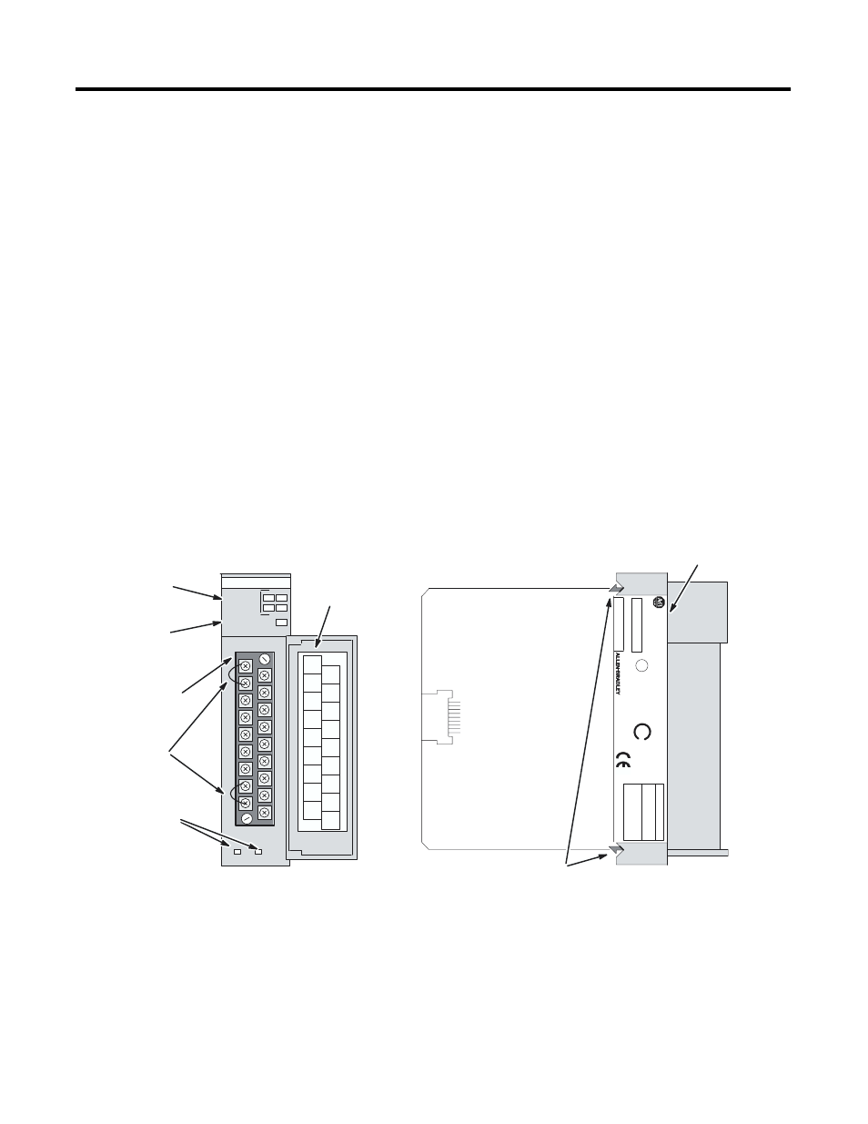
Page 14: Self-locking tabs, Side label removable terminal block, Door label cjc sensors
Publication 1746-UM007C-EN-P - July 2004
1-2 Overview
Hardware Features
The thermocouple module fits into any single-slot, except the
processor slot (0), in either an SLC 500 modular system or an SLC 500
fixed system expansion chassis (1746-A2). It is a Class 1 module (uses
8 input words and 8 output words). It interfaces to thermocouple
types J, K, T, E, R, S, B, and N, and supports direct ±50 mV and ±100
mV analog input signals.
The module requires the use of Block Transfer in a remote
configuration.
The module contains a removable terminal block providing
connection for four thermocouple and/or analog input devices. There
are also two, cold-junction compensation (CJC) sensors used to
compensate for offset voltages introduced into the input signal as a
result of the cold-junction, i.e., where the thermocouple wires connect
to the module wiring terminal. There are no output channels on the
module. Module configuration is done via the user program. There are
no DIP switches.
Cable Tie Slots
SLC 500
CA
T
SERIAL
NO.
INPUT
Self-Locking Tabs
THERMOCOUPLE/mV INPUT MODULE
MADE IN USA
Side Label
Removable
Terminal Block
FAC 1M
INPUT
SIGNAL
RANGES
THERMOCOUPLE TYPES:
VOL
TAGE:
100mVDC to +100mVDC
CJC A+
SHIELD
SHIELD
SHIELD
SHIELD
CHL3
CHL3+
CHL2
CHL2+
CHL1
CHL1+
CHL0
CHL0+
Door Label
CJC Sensors
Do Not
Remove
CJC A
Do Not
Remove
CJC B
Do Not
Remove
CJC B+
Do Not
Remove
SHIELD
ANLG
50mVDC to +50mVDC
SER
FRN
U
L
LISTED IND. CONT
. EQ.
FOR HAZ. LOC.
A196
CLASS I, GROUPS
A, B,
C
AND D, DIV
.2
OPERA
TING
SA
J, K,
T, E, R, S, B, N
TEMPERA
TURE
CODE T3C
MODULE STATUS
0
1
2
3
CHANNEL
STATUS
THERMOCOUPLE/mV
1746 NT4
NT4-xxx x
Channel Status
LEDs (Green)
Module Status
LED (Green)
COM
_
_
_
_
_
_
®
®
_
_