Tools and equipment, 6–2 calibrating your module, Thermocouple or sensor – Rockwell Automation 1794-IT8,D17946.5.7 Thermocouple/Millivolt Input Module User Manual
Page 44: Decade box voltage source, Thermocouple or sensor disconnected
6–2
Calibrating Your Module
Publication 1794-6.5.7 – April 1997
In order to calibrate your thermocouple input module you will need
the following tools and equipment:
Tool or Equipment
Description
Precision Voltage Source
or
0–100mV, 1
µ
V resolution
Analogic 3100, Data Precision 8200
or equivalent
or
Thermocouple Simulator
and Calibration source
Thermocouple Simulator/Calibrator
Model 1120
Ectron Corporation
8159 Engineer Road
San Diego, CA 92111-1980
Industrial Terminal and
Interconnect Cable
Programming terminal for A–B family processors
The thermocouple/mV module has open circuit detection. This is
accomplished by a 1
µ
A current source in the module. This current
flowing through the lead wire or thermocouple extension wire
generates an error or offset voltage in the reading. Use the “Error
Due to Open Circuit Current Through Loop Resistance” in appendix
A to determine if the magnitude of the error is acceptable.
Calibrate this error out as follows:
17
18
19
20
21
22
23
24
25
26
27
28
29
30
31
32
33
0
1
2
3
4
5
6
7
8
9
10
11
12
13
14
15
16
1
2
3
4
5
6
7
8
9
10
11
12
13 14
15
0
35
36
37
38
39
40
41
42
43
44
45
46
47
48
49
50
51
34
1794-TB3, -TB3T
0 –15
34–51
16–33
A
B
C
Ω
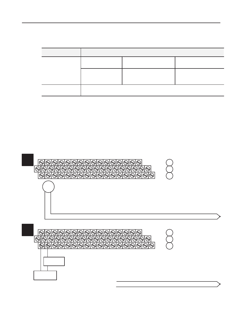
b. Measure total loop resistance of both lead/extension wires and thermocouple.
1
Thermocouple
or
Sensor
c. If using a sensor other than a thermocouple, disconnect the lead wires at the
sensor and tie together for this measurement. Reconnect after measurement.
d. After measuring, remove ohmmeter.
a. Disconnect the lead wires at the terminal base unit.
17
18
19
20
21
22
23
24
25
26
27
28
29
30
31
32
33
0
1
2
3
4
5
6
7
8
9
10
11
12
13
14
15
16
1
2
3
4
5
6
7
8
9
10
11
12
13 14
15
0
35
36
37
38
39
40
41
42
43
44
45
46
47
48
49
50
51
34
1794-TB3, -TB3T
0 –15
34–51
16–33
A
B
C
a. Set decade box to value determined in step 1, and connect in series with a preci-
sion voltage source.
2
Decade Box
Voltage Source
b. Connect to the input terminals of the particular channel you are calibrating.
c. Perform an offset and gain calibration as outlined later in this chapter.
Thermocouple
or
Sensor
Disconnected
Tools and Equipment
Removing Lead Wire or
Thermocouple Extension
Wire Resistance