A b c – Rockwell Automation 1794-IT8,D17946.5.7 Thermocouple/Millivolt Input Module User Manual
Page 20
2–6
How to Install Your Thermocouple/mV Input Module
Publication 1794-6.5.7
!
ATTENTION: The Thermocouple/mV module does
not receive power from the backplane. +24V dc power
must be applied to your module before installation. If
power is not applied, the module position will appear
to the adapter as an empty slot in your chassis.
4. On 1794-TB3T terminal base units: Connect the cold junction
compensation (CJC) wiring to terminals 36, 37 and 38 for inputs
0 through 3, and terminals 47, 48 and 49 for inputs 4 through 7.
Connect the tail of the cold junction compensator to any of the
associated thermocouple input terminals: 0 through 7 for CJC
connected to 36, 37 and 38; or 8 through 15 for CJC connected to
47, 48 and 49. The tail of the cold junction compensator shares
a terminal with an input.
5. If daisy chaining the +24V dc power to the next base unit,
connect a jumper from terminal 51 on this base unit to terminal
34 on the next base unit.
17
18
19
20
21
22
23
24
25
26
27
28
29
30
31
32
33
0
1
2
3
4
5
6
7
8
9
10
11
12
13
14
15
16
1
2
3
4
5
6
7
8
9
10 11 12 13 14
15
0
35
36
37
38
39
40
41
42
43
44
45
46
47
48
49
50
51
34
1794-TB3, -TB3T
0 –15
34–51
16–33
A
B
C
1
51
34
17
18
19
20
21
22
23
24
25
26
27
28
29
30
31
32
33
0
1
2
3
4
5
6
7
8
9
10
11
12
13
14
15
16
0 –15
34–51
16–33
1
2
3
4
5
6
7
8
9
10 11 12 13 14
15
0
1794-TB2
A
B
C
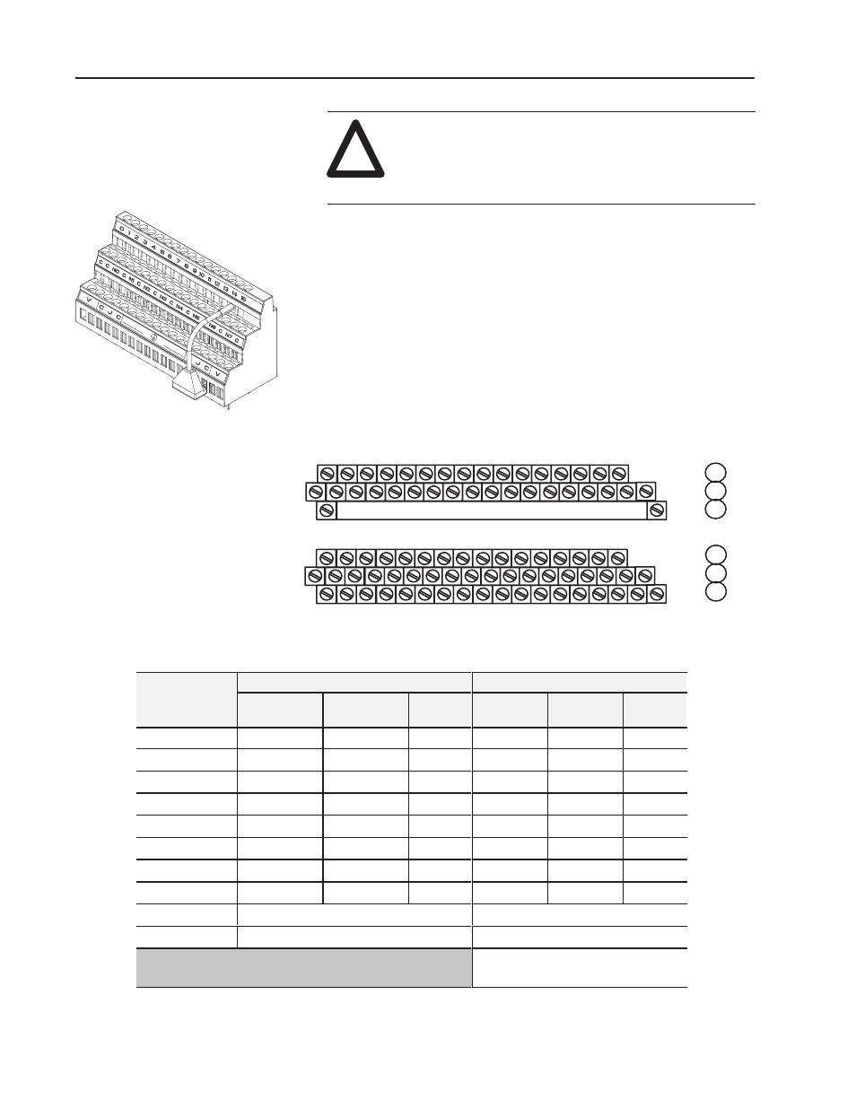
Table 2.A
Wiring connections for the 1794-IT8 Thermocouple Input Module
Thermocouple
1794-TB2, -TB3 Terminal Base Units
1794-TB3T Terminal Base Unit
2
Thermocouple
Channel
High Signal
Terminal (+)
Low Signal
Terminal (–)
Shield
Return
High Signal
Terminal (+)
Low Signal
Terminal (–)
Shield
Return
1
0
0
1
17
0
1
39
1
2
3
19
2
3
40
2
4
5
21
4
5
41
3
6
7
23
6
7
42
4
8
9
25
8
9
43
5
10
11
27
10
11
44
6
12
13
29
12
13
45
7
14
15
31
14
15
46
24V dc Common
16 thru 33
16, 17, 19, 21, 23, 25, 27, 29, 31 and 33
+24V dc power
1794-TB2 – 34 and 51; 1794-TB3 – 34 thru 51
34, 35, 50 and 51
1
Terminals 39 to 46 are chassis ground.
2
r inal 36 37 3 an 47 4 49 ar col unction
2
Terminals 36, 37, 38 and 47, 48, 49 are cold junction
compensator terminals.
Cold Junction Compensator
Pt.No. 969424-01