Example block transfer programs – Rockwell Automation 1771-IJ_IK IK ENCODER/COUNTER MODULES User Manual
Page 49
6–5
Block Transfer Programming
Publication 1771ĆUM006B-EN-P - June 2002
Note that there is no identifying bit pattern to distinguish preset
words #1 and #2 from each other. The encoder/counter module
identifies these words by their order of transmission in block
transfer. As these words are stored in memory, preset word #1 is
stored in the word immediately following the output control word.
Preset word #2 is then stored in the word immediately following
preset word #1.
The module communicates with any Allen-Bradley processor that
has block transfer capability. The module is a bidirectional block
transfer module. Bidirectional means that the module performs both
read and write block transfer operations. You transfer data from
your module to the processor’s data table with a block transfer read
(BTR) instruction. You transfer data to your module from the
processor’s data table with a block transfer write (BTW) instruction.
PLCĆ2 Family Processors
The following examples use block transfer instructions to perform
block transfers. However, the Mini-PLC-2 (cat. no. 1772-LN3) and
PLC-2/20 (cat. no. 1772-LP1,-LP2) processors use multiple GET
instructions to perform block transfers. Refer to the processor user’s
manual for an explanation of multiple GET block transfer.
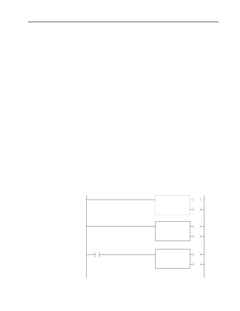
The generalized and example programs (Figure 6.3 and Figure 6.4)
demonstrate the use of a single block transfer read (BTR) and a
single block transfer write (BTW) to pass data between the processor
and the module.
Figure 6.3
Generalized Ladder Logic for PLCĆ2 Block Transfer
EN
BTW
File AAA-BBB
DN
EN
BTR
File CCC-DDD
DN
EN
FFM
File CCC-DDD
DN
File EEE-FFF
BTR
DN
1
2
1 = source
2 = destination
15962
Example Block Transfer
Programs