Rockwell Automation 1771-IJ_IK IK ENCODER/COUNTER MODULES User Manual
Page 46
6–2
Block Transfer Programming
Publication 1771ĆUM006B-EN-P - June 2002
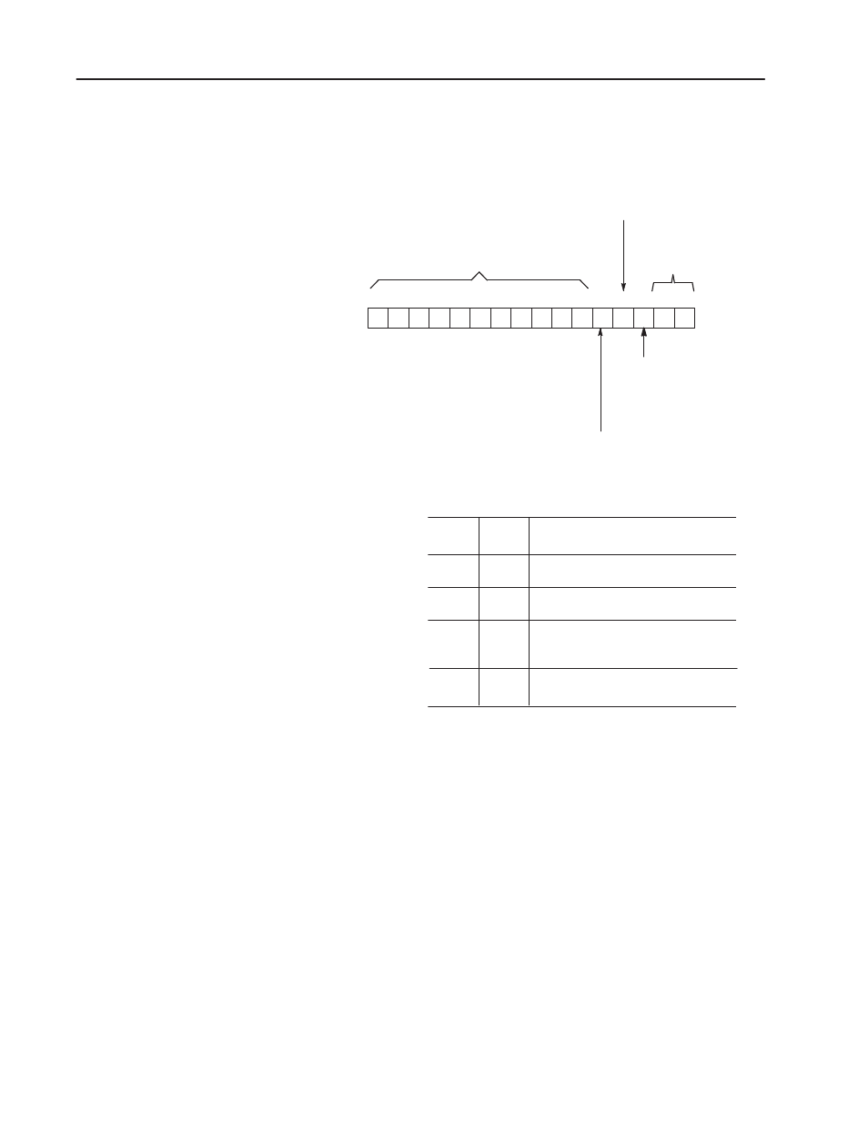
Figure 6.1
Control Word Ć Block Transfer Mode
ЙЙ
ЙЙ
ЙЙ
ЙЙ
ЙЙ
ЙЙ
ЙЙ
ЙЙ
ЙЙ
ЙЙ
ЙЙ
ЙЙ
ЙЙ
ЙЙ
ЙЙ
ЙЙ
ЙЙ
ЙЙ
ЙЙ
ЙЙ
ЙЙ
ЙЙ
17 16 15 14 13 12 11 10 07 06 05 04 03 02 01 00
BIT
01
BIT
00
FUNCTION
Count.
0
0
0
1
1
0
1
1
Reset and hold the accumulated
count at 000.
Return the accumulated count to
000 and begin counting
immediately.
Invalid, module executes previously
programmed function.
Table Function Control Bits
Bits 00Ć01 Function
Control (See Table)
Bit 03, Up/down
1 = count up
0 = count down
(Significant in counter mode only)
Bit 02, Enable outputs
1 Ć Enable
0 Ć Disable
Bit 04, Home Latch Enable
1 Ć Enable
0 Ć Disable
Bits 05Ć17, Not used.
May have any setting
15960
Bit 04 is the home latch enable bit.
The module resets the count to zero when all three of the following
conditions are true:
•
Home latch enable bit (bit 04) is set to 1.
•
Marker input is high.
•
Home limit switch is closed (limit switch LED is on).
The count remains at zero until one or more of these conditions go
false. Then module operation follows the function control bits
described in Figure 6.1.
- 20P PowerFlex DC Drive - Frame D Bimetal Thermostat (10 pages)
- 1336S_F_T_E_R F Frame Snubber Resistor Repl. (6 pages)
- 22-COMM PowerFlex 4-Class DSI (Drive Serial Interface) Network Communication Adapter (4 pages)
- 8-545 Plug In Solid State Relay (2 pages)
- 20-HIM-B1 PowerFlex 7-Class HIM Bezel (DPI) (4 pages)
- 100 Contactors with DC Coil (1 page)
- 100 Contactors with DC Coil (2 pages)
- 20P PowerFlex DC Drive - Frame D Switching Power Supply Circuit Board (6 pages)
- 140G-MTFx_MTHx_MTIx_MTKx Trip Unit Installation-140G-M (6 pages)
- 45BRD Analog Laser Sensor (4 pages)
- 20D Multi-Device Interface Option Board for PowerFlex 700S Drives (20 pages)
- 56RF RFID 18 mm Cylindrical Transceiver (2 pages)
- 42KC Miniature Rectangular: 5V DC Version (2 pages)
- 20P PowerFlex DC Drive - Frame A Switching Power Supply Circuit Board (16 pages)
- 21P-MISC-A-TP-2 Transition Tube Kit #C19-6/7 For PowerFlex 755 w/OEM Liquid Cooling Fr 6/7 Drive (2 pages)
- 42BT Background Suppression Sensor (3 pages)
- 42CB High Speed 18mm Cylindrical (4 pages)
- 140EX-JE2_JE3 Molded Case Circuit Breaker (4 pages)
- 140G-K-EAM1A Early Make Aux Contact for Rotary Handle Oper Mech-140G-K (1 page)
- 140G-K-EAM1A Early Make Aux Contact for Rotary Handle Oper Mech-140G-K (3 pages)
- 20-HIM-A6 PowerFlex (Human Interface Module) (74 pages)
- 42CF General Purpose 12mm Cylindrical (4 pages)
- 20D PowerFlex 700S Phase II Drive Frames 1...6 (80 pages)
- 140EX-HE1_HE2 Molded Case Circuit Breaker (6 pages)
- 140EX-HE1_HE2 Molded Case Circuit Breaker (4 pages)
- 20B PowerFlex 700 Custom Firmware - Pump Off (12 pages)
- 20-WIM-N4S DPI Wireless Interface Module (92 pages)
- 140U H-Frame Circuit Breaker Fixed and Adjustable Thermal Trip (7 pages)
- 140U H-Frame Circuit Breaker Fixed and Adjustable Thermal Trip (2 pages)
- 60-2619, 42JS Swivel/Tilt Mounting Bracket (1 page)
- 22A PowerFlex 4/40/400 Flange Mount (4 pages)
- 45MLA Controller Installation Instructions (16 pages)
- 20P PowerFlex DC Drive - Cooling Fan for Frame A Drives Above 73A at 230V 460V AC (6 pages)
- 42JS Series 7000 to 42JS VisiSight Replacement Kit (2 pages)
- 22A PowerFlex 4-Class HIM Bezel (DSI) (4 pages)
- 42CS Stainless Steel Photoelectric Sensors (4 pages)
- 20L-LL PowerFlex 700L Liquid-to-Liquid Heat Exchanger (40 pages)
- 20P PowerFlex DC Drive - Frame B SCR Modules (20 pages)
- 22B PowerFlex 40 Quick Start FRN 5.xx - 6.xx (161 pages)
- 22B PowerFlex 40 Quick Start FRN 5.xx - 6.xx (22 pages)
- 22F PowerFlex 4M Input RFI Filters (2 pages)
- 45LFM Capacitive Label Sensor (4 pages)
- 140G-Rx Installation Instruction-140G-R (2 pages)
- 140G-Rx Installation Instruction-140G-R (29 pages)
- 22C PowerFlex 400 AC Drive Quick Start - FRN 1-4.xx (28 pages)