1771ćik – Rockwell Automation 1771-IJ_IK IK ENCODER/COUNTER MODULES User Manual
Page 17
2–5
Preliminary Adjustments
Publication 1771ĆUM006B-EN-P - June 2002
No special filtering is provided on channel B, since the filtering
necessary for a mechanical switch would defeat the purpose of a very
fast count direction change that is not dependent on the processor
scan time. Therefore, a transistor switch or gate should be used to
pull the channel B input low. The gate or switch must sink 14ma of
current to pull the channel B input low. The count changes direction
in less than 0.01ms from the time channel B input changes state.
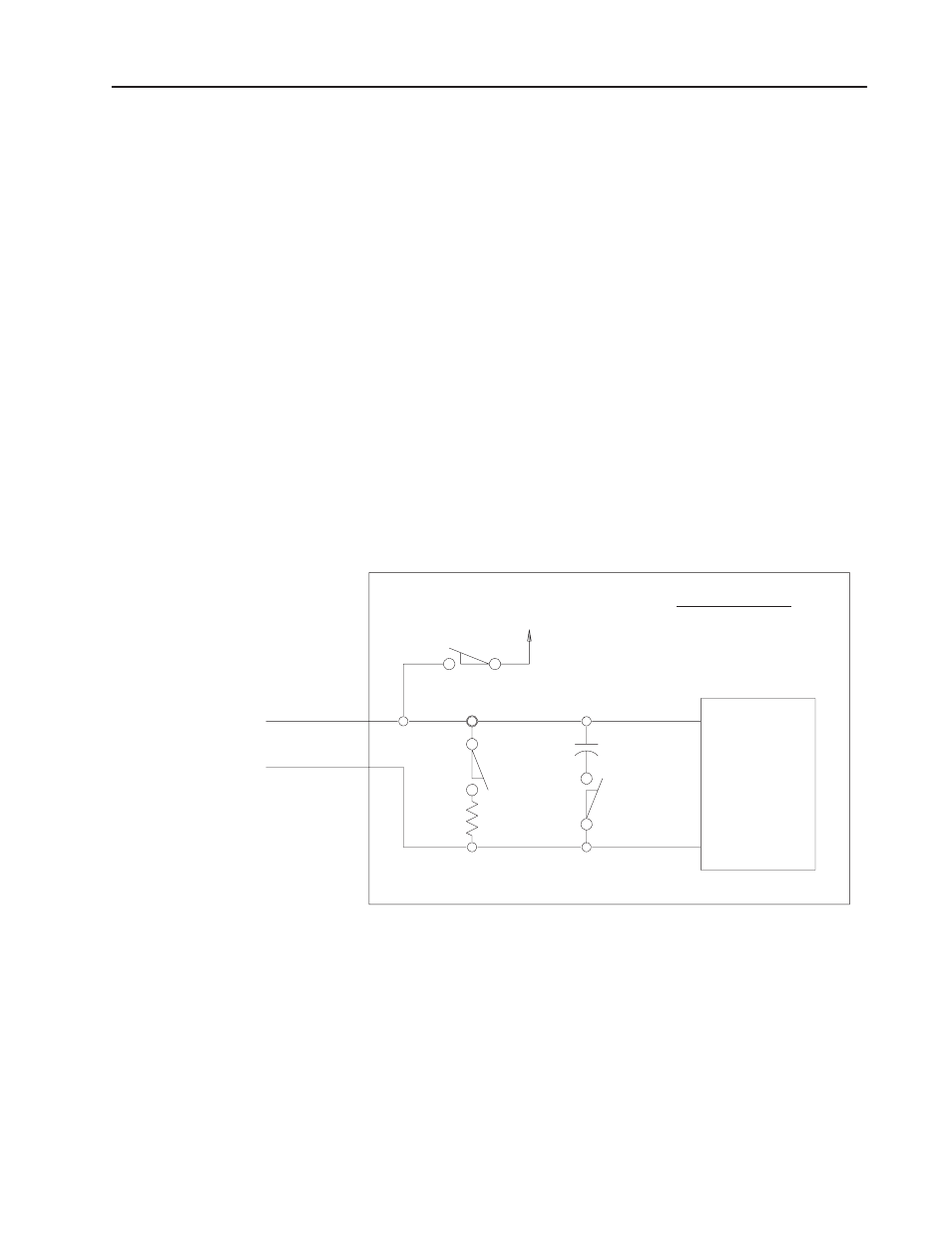
The 1771-IK module is designed to accept several types of devices
that will operate in the 12 to 24V dc range (Figure 2.2). Since most
high voltage quadrature encoder outputs produce signals through an
open collector output, the module is configured for a pull-up on
channel B. Channel A must be set for a pull-up by setting switch 1
on and switch 2 off. Some counting devices may also use a pull-up
arrangement.
Figure 2.2
Input Configuration for Channel A of the 1771ĆIK Showing Functions of Switch
Assembly SWĆ2
Channel A
Common
Channel A
Switch 1
Module
Switch 1 -- Pull up
Switch 2
Switch 3
Sensing
15946
External Voltage
Circuits
Switch 2 -- Pull down
Switch 3 -- Filter
Switch Assembly SW2
The settings on the input configuration switch assembly SW-2 are
not the same on the 1771-IJ as they are for 1771-IK. Refer to
Table 2.D for switch settings.
1771ĆIK