Status indicators – Rockwell Automation 1771-IJ_IK IK ENCODER/COUNTER MODULES User Manual
Page 11
1–3
Introduction
Publication 1771ĆUM006B-EN-P - June 2002
The encoder/counter module is shipped with two 12 terminal
gold-plated Field Wiring Arms (cat. no. 1771-WB).
Unless otherwise noted, this manual refers to both versions of the
module.
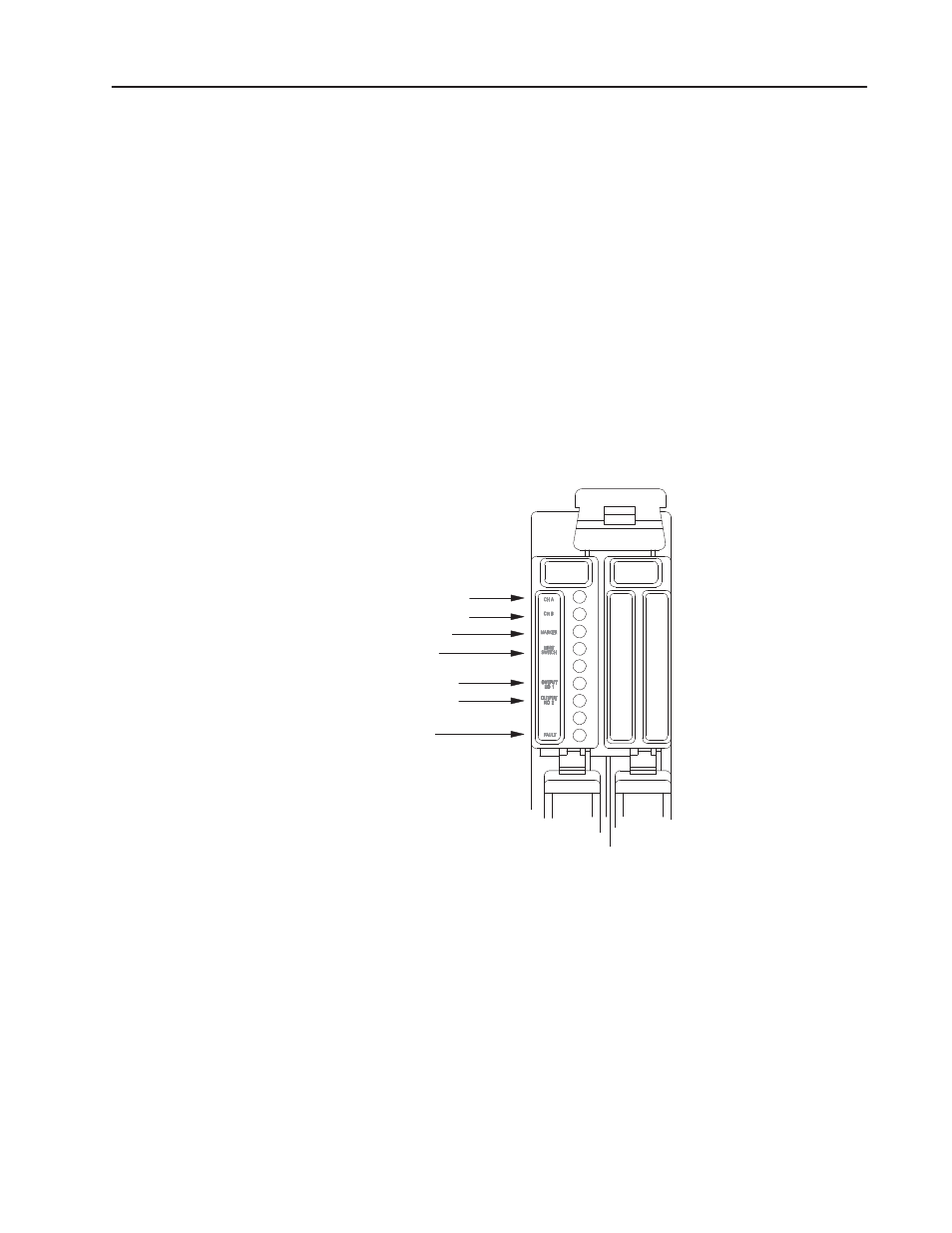
There are seven status indicators (Figure 1.2) on the front of the left
half of the module. The four indicators, corresponding to channel A,
channel B, marker, and switch inputs, illuminate when their
respective input signals are high. The next two indicators show the
state of the outputs. An output indicator is on when the output
circuit is activated. The bottom indicator illuminates when the
module detects a fault.
Figure 1.2
Red LED Status Indicators
Channel A
Channel B
Marker
Limit
Output 1
Output 2
Fault
15943
When system power is turned on, the module runs a self-test. During
power-up, it is normal for the fault indicator to flash on momentarily.
If the FAULT LED does not turn off, the module has detected a fault.
The self-test includes checks to make sure that all counters and
registers have been reset to zero and memory is cleared. If a
breakdown of communication occurs during block transfer, the
FAULT LED will also light. Bit 14, the diagnostic bit in the input
status word, is also set anytime the FAULT LED is on.
After power-up, the module will stay in its reset state (outputs
disabled and counter held reset) until the necessary control bits are
set in the program.
Status Indicators