Outputs words input status word – Rockwell Automation 1771-IJ_IK IK ENCODER/COUNTER MODULES User Manual
Page 28
4–2
Module/Processor Communication
Publication 1771ĆUM006B-EN-P - June 2002
The program controls encoder/counter module operation through the
output words. These words function as follows:
•
Control word – the control word, as its name implies, instructs the
module on its operation and on control of its own outputs. By
setting specific control word bits, you set up the module’s initial
mode of operation and can subsequently alter module operation
as the application requires.
•
Preset words #1 and #2 – the optional preset words are values that
can be used for comparison by the module. When these words
are used, the module controls its own output based on comparison
between its accumulated count preset values. You can use these
words to direct module control of its own output terminals,
independent of the timing of the processor I/O and program
scans.
Stored in the data table, these output words are sent to the module as
controlled by the program. The storage and transmission of these
words to the module differ depending on whether single transfer or
block transfer programming is used. In addition, the bit–by–bit
significance of these words is dependent on the data transfer method
used. For this reason, specific information on the storage and
composition of these words is given separately in the following
chapters which describe each programming method.
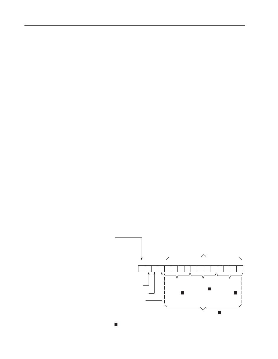
The input status word is the single input word received from the
encoder/counter module. This word has the same format for both
block and single transfer programming. The input status word has
the format of Figure 4.2.
Figure 4.2
Input Status Word - Single Transfer and Block Transfer
17 16 15 14 13 12 11 10 07 06 05 04 03 02 01 00
Bit 16, carry bit
Bit 15, borrow bit
Bit 14, diagnostic bit
1 = module fault detected
0 = normal operation
Most
Significant
BCD Digit
(0-9)
Middle
BCD Digit
(0-9)
Least
Significant
BCD Digit
(0-9)
or, 12-bit binary value
Module switch selection dtermines whether bits 00Ć13 are of binary or BCD format
Module
Accumulated
Count
15951
Bit 17, home bit
Set to 1 when:
Marker input high
and
limit switch input TRUE
and
Home latch enable bit is
set ON in control word
1
1
1
1
1
Outputs Words
Input Status Word