Example program ć single transfer – Rockwell Automation 1771-IJ_IK IK ENCODER/COUNTER MODULES User Manual
Page 42
5–12
Single Transfer Programming
Publication 1771ĆUM006B-EN-P - June 2002
Note: In some applications, it may be feasible to designate an input
location for the purpose of scan counter control. In this instance, an
on-delay timer (TON) instruction can be used to multiplex output
data to the encoder/counter module. A timer with 0.1-second
resolution is acceptable for this purpose. Each step of Table 5.A can
be programmed to be executed at a 0.1-second interval from the
previous step.
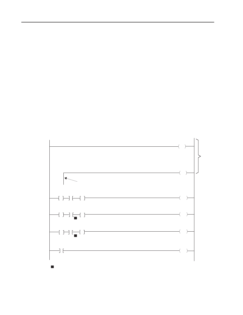
Figure 5.8 is an example program for single-transfer multiplexing of
output words to the encoder/counter module. This example uses the
type of scan counter recommended for PLC-2 processors. However,
the general format of these rungs would be the same for a PLC
processor, with addressing differences, substitution of the type of
scan counter shown in Figure 5.7, and other minor changes.
Figure 5.8
Example Program Ć Single Transfer
030
CTU
PR003
AC000
030
CTU
PR003
AC000
Branch End Instruction
012
PUT
030
201
051
001
012
PUT
030
202
052
002
012
PUT
030
203
053
003
030
03015
Scan
Counter
Output
Control
Word
Output
Preset
Word #1
Output
Reset
Preset
Word #2
Scan
Counter
For the PLC processor, values of constants would be 003 in rung 4, 005 in rung 5.
Rung
No.
1
2
3
4
5
6
15959
G
G
G
G
G
G
=
=
=
1
1
1
CTR
Example Program Ć Single
Transfer