Rockwell Automation 1771-IJ_IK IK ENCODER/COUNTER MODULES User Manual
Page 32
5–2
Single Transfer Programming
Publication 1771ĆUM006B-EN-P - June 2002
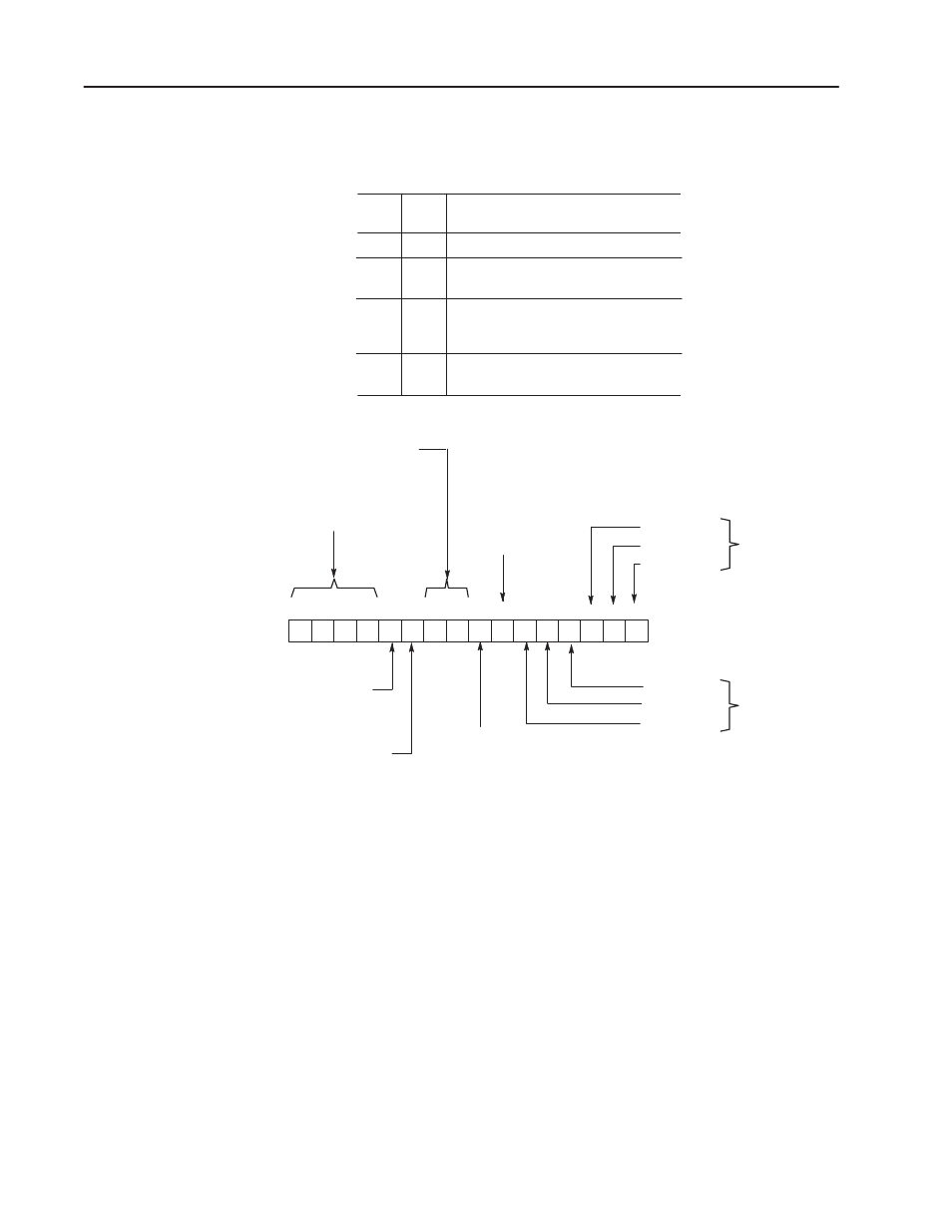
Figure 5.1
Control Word Ć Single Transfer
17 16 15 14 13 12 11 10 07 06 05 04 03 02 01 00
1 0 0 0
Bit 06,
Not Used
AC > PR #1
AC = PR #1
AC < PR #1
AC < PR #2
AC = PR #2
AC > PR #2
Bit 07, Home
Latch Enable
1 = Enable
0 = Disable
BIT
11
0
0
1
1
BIT
10
0
1
0
1
FUNCTION
Count
Reset, and hold the accumulated
count at 000.
Return the accumulated count to
000 and begin counting
immediately.
Invalid, module executes previously
programmed function.
Bits 14Ć17, Word Select Bits.
Must have this pattern for control
word.
Bits 10Ć11, Function
Control (see table)
Bits 00Ć02,
Comparison
Parameters for
Preset #1
1 = True
0 = False
Bits 03Ć05,
Comparison
Parameters for
Preset #2
1 = True
0 = False
(Counter Mode Only )
Bit 13, Up/Down
1 = Count Up
0 = Count Down
Bit 12, Enable Outputs
1 = Enable
0 = Disable
15952
Function Control Bits
Bits 14-17 of this word are word select bits. These bits must have
the setting shown in Figure 5.1 to identify the word as the output
control word.
Bit 13 of this word is the up/down bit. This bit is significant only
when the module is used in the counter mode. The state of this bit
controls module function as follows:
1 -The module increments its accumulated count with each count
received on channel A.
0 -The module decrements its accumulated count with each received
on channel A.